Manuals
/
Fender
/
Home Audio
/
Stereo Amplifier
Fender
T5A125V
manual
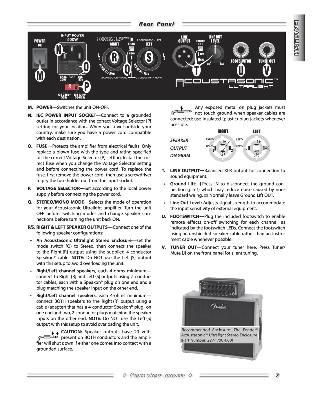
Rear Panel, Speaker Output Diagram
Models:
T5A125V
1
7
28
28
Download
28 pages
59.77 Kb
4
5
6
7
8
9
10
11
Specs
Speaker Output Diagram
Features include
Page 7
Image 7
Page 6
Page 8
Page 7
Image 7
Page 6
Page 8
Contents
Page
ITALIANO- PAGINE
ENGLISH- PAGES
ESPAÑOL- PAGINAS
FRANÇAIS- PAGES
Page
I m p o r t a n t i I s t r u z i o n i p e r l a S i c u r e z z a
Page
Acoustasonic Ultralight Amplifier
Features include
Front Panel
Rear Panel
SPEAKER OUTPUT DIAGRAM
MIC CHANNEL EFFECTS
Specifications
Effects Descriptions
INSTRUMENT CHANNEL EFFECTS
Panel frontal
Amplificador Acoustasonic Ultralight
Características incluidas
Panel trasero
DIAGRAMA DE SALIDA DE ALTAVOZ
EFECTOS DEL CANAL DE MICRO
Descripción de los efectos
Especificaciones técnicas
EFECTOS DEL CANAL DE INSTRUMENTOS
Face avant
Amplificateur Acoustasonic Ultralight
Caractéristiques générales
CÂBLAGE DES SORTIES HAUT-PARLEUR
Face arrière
EFFETS DU CANAL MICRO
Descriptions des effets
Caractéristiques techniques
EFFETS DU CANAL INSTRUMENT
Acoustasonic Ultralight Amplifier
Pannello frontale
Pannello posteriore
SPEAKER USCITA DIAGRAMMA
EFFETTI CANALE MIC
Descrizione degli effetti
Specifiche
EFFETTI CANALE INSTRUMENT
Acoustasonic Ultralight-Verstärker
Features
Vorderseite
Rückseite
BOXEN AUSGANGS DIAGRAMM
MIKROFON-KANAL
Effekt-Beschreibungen
Technische Daten
INSTRUMENTEN-KANAL
Características Incluem
Painel Frontal
Amplificador Acoustasonic Ultralight
Painel Traseiro
DIAGRAMA DE SAÍDA DE ALTO-FALANTE
EFEITOS DE CANAL MIC
Descrições dos Efeitos
Especificações
EFEITOS DE CANAL DO INSTRUMENTO
フロントパネル
Acoustasonic Ultralight アンプリファイアー
R/S. RIGHT & LEFT(右/左)スピーカー出力端子
リアパネル
500W
スピーカー
エフェクト詳細
Page
2005 FMIC. All rights reserved
FENDER MUSICAL INSTRUMENTS CORPORATION
A PRODUCT OF
CORONA, CALIFORNIA USA
Top
Page
Image
Contents