4.1Component Checking Procedure
Number Procedure
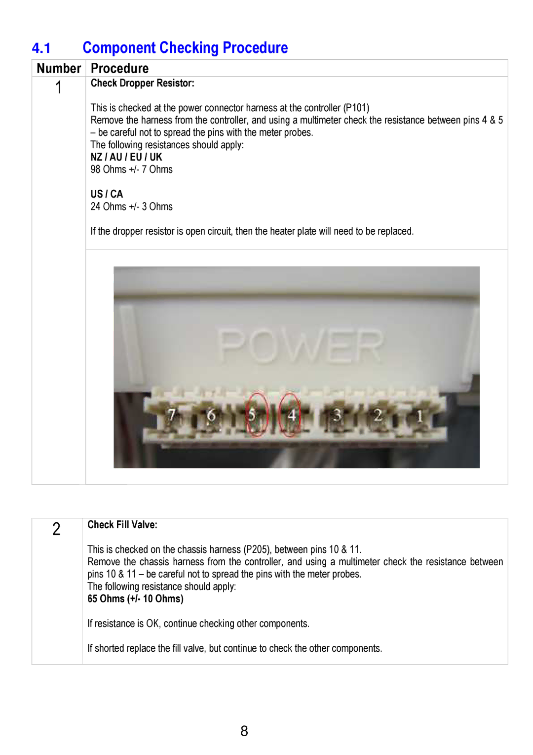
1Check Dropper Resistor:
This is checked at the power connector harness at the controller (P101)
Remove the harness from the controller, and using a multimeter check the resistance between pins 4 & 5
–be careful not to spread the pins with the meter probes. The following resistances should apply:
NZ / AU / EU / UK
98 Ohms +/- 7 Ohms
US / CA
24 Ohms +/- 3 Ohms
If the dropper resistor is open circuit, then the heater plate will need to be replaced.
2
Check Fill Valve:
This is checked on the chassis harness (P205), between pins 10 & 11.
Remove the chassis harness from the controller, and using a multimeter check the resistance between pins 10 & 11 – be careful not to spread the pins with the meter probes.
The following resistance should apply:
65 Ohms (+/- 10 Ohms)
If resistance is OK, continue checking other components.
If shorted replace the fill valve, but continue to check the other components.
8