BP7335 Palazzo 1/9/07 9:05 AM Page 5
Electrical Requirements | Ceiling Fan Procedures |
IMPORTANT: Your ceiling fan will not function properly, and may be damaged, if used with any wall dimmer switch or control other than the Emerson Electric Fan/Light Wall Control supplied with the fan, or an optional Emerson Electric SW110 Remote Control.
Your new ceiling fan will require a grounded electrical supply line of 120 volts AC, 60 Hz, 15 amp circuit.
The outlet box must be securely anchored and capable of withstanding a load of at least 50 pounds.
!WARNING
To reduce the risk of fire, electric shock, or personal injury, mount fan to outlet box marked “Acceptable for Fan Support of 50 Lbs. or Less”, and use screws supplied with outlet box. Most outlet boxes commonly used for support of light fixtures are not acceptable for fan support and may need to be replaced. Consult a qualified electrician if in doubt.
If your fan is to replace an existing ceiling light fixture, turn electricity off at the main ![]() fuse or circuit breaker box at this time and remove the existing light fixture.
fuse or circuit breaker box at this time and remove the existing light fixture.
!WARNING
Turning off wall switch is not sufficient. To avoid possible electrical shock, be sure electricity is turned off at the main fuse or circuit breaker box before wiring. All wiring must be in accordance with National and Local codes and the ceiling fan must be properly grounded as a precaution against possible electrical shock.
General
Your Emerson ceiling fan comes supplied with a Fan/Light Wall Control which consists of a SW113 wall control (transmitter) and a SW105 remote control receiver mounted under the ceiling cover. This system allows you to regulate your ceiling fan speed and light intensity.
NOTE: An optional Emerson Electric SW110 Remote Control may also be used to control your ceiling fan.
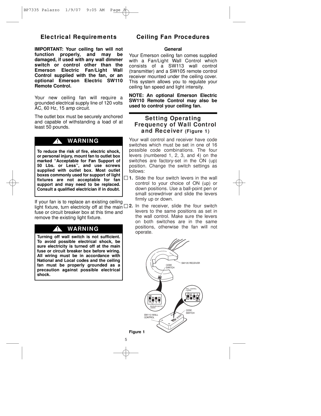
Setting Operating
Frequency of Wall Control
and Receiver (Figure 1)
Your wall control and receiver have code switches which must be set in one of 16 possible code combinations. The four levers (numbered 1, 2, 3, and 4) on the switches are
1.Slide the four switch levers in the wall control to your choice of ON (up) or down positions. Use a
2.In the receiver, slide the four switch levers to the same positions as set in the wall control. Make sure the levers on both switches are in the same positions, otherwise the fan will not operate.
![]() SW105 RECEIVER
SW105 RECEIVER
CODE
SWITCH
ON
1![]() 2 3 4
2 3 4
RECEIVER SWITCH
LEVERS
SW113 WALL CONTROL
WALL CONTROL
LEVERS
4 | 3 | 2 | 1 |
|
|
| ON |
CODE
SWITCH
Figure 1
5