BP7335 Palazzo 1/9/07 9:05 AM Page 7
![]()
![]() 4. Install a wall control in the wall box containing the “hot” wire first. Connect one black wire of the wall control to the “hot” wire. Securely connect wires with wire connectors supplied.
4. Install a wall control in the wall box containing the “hot” wire first. Connect one black wire of the wall control to the “hot” wire. Securely connect wires with wire connectors supplied.
![]()
![]() 5. Connect the other black wire of the wall control to both remaining traveler wire(s) in the wall box and secure with wire connector supplied.
5. Connect the other black wire of the wall control to both remaining traveler wire(s) in the wall box and secure with wire connector supplied.
NOTE: Retrofit
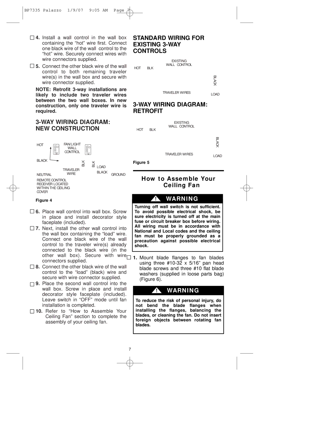
STANDARD WIRING FOR EXISTING
EXISTING
WALL CONTROL
HOT BLK |
|
| BLACK |
TRAVELER WIRES | LOAD |
|
3-WAY WIRING DIAGRAM: RETROFIT
3-WAY WIRlNG DIAGRAM: NEW CONSTRUCTION
EXISTING
WALL CONTROL
HOT BLK
HOT |
| FAN/LIGHT |
|
|
| BLACK |
|
| WALL |
|
|
|
|
| EMERSON | CONTROL | EMERSON |
| TRAVELER WIRES |
|
|
|
|
|
| LOAD | |
BLACK |
|
|
|
|
| |
| BLK |
| BLK | Figure 5 |
| |
|
|
|
|
| ||
|
| TRAVELER |
| LOAD |
|
|
|
|
| BLACK |
|
| |
NEUTRAL |
| WIRE |
| GROUND |
| |
|
|
|
| |||
REMOTE CONTROL |
|
| How to Assemble Your | |||
RECEIVER LOCATED |
|
| Ceiling Fan |
| ||
WITHIN THE CEILING |
|
|
| |||
COVER |
|
|
|
|
|
|
Figure 4 | ! WARNING |
![]()
![]() 6. Place wall control into wall box. Screw in place and install decorator style faceplate (included).
6. Place wall control into wall box. Screw in place and install decorator style faceplate (included).
7. Next, install the other wall control into the wall box containing the “load” wire. Connect one black wire of the wall control to the traveler wire(s) already connected to the black wire (in the other wall box). Secure with wire connectors supplied.
8. Connect the other black wire of the wall control to the “load” (black) wire and secure with wire connector supplied.
![]()
![]() 9. Place the second wall control into the wall box. Screw in place and install decorator style faceplate (included).
9. Place the second wall control into the wall box. Screw in place and install decorator style faceplate (included).
Leave switch in “OFF” mode until fan installation is completed.
![]()
![]() 10. Refer to “How to Assemble Your Ceiling Fan” section to complete the assembly of your ceiling fan.
10. Refer to “How to Assemble Your Ceiling Fan” section to complete the assembly of your ceiling fan.
Turning off wall switch is not sufficient. To avoid possible electrical shock, be sure electricity is turned off at the main fuse or circuit breaker box before wiring. All wiring must be in accordance with National and Local codes and the ceiling fan must be properly grounded as a precaution against possible electrical shock.
1.Mount blade flanges to fan blades using three
!WARNING
To reduce the risk of personal injury, do not bend the blade flanges when installing the flanges, balancing the blades, or cleaning the fan. Do not insert foreign objects between rotating fan blades.
7