INSTALLATION
SINK DRAIN ASSEMBLY INSTRUCTIONS (OPTIONAL)
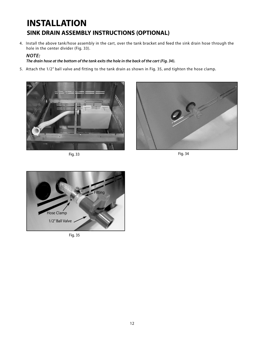
4.Install the above tank/hose assembly in the cart, over the tank bracket and feed the sink drain hose through the hole in the center divider (Fig. 33).
NOTE:
The drain hose at the bottom of the tank exits the hole in the back of the cart (Fig. 34).
5. Attach the 1/2” ball valve and fitting to the tank drain as shown in Fig. 35, and tighten the hose clamp.
Fig. 33 | Fig. 34 |
Fitting
Hose Clamp
1/2” Ball Valve
Fig. 35
12