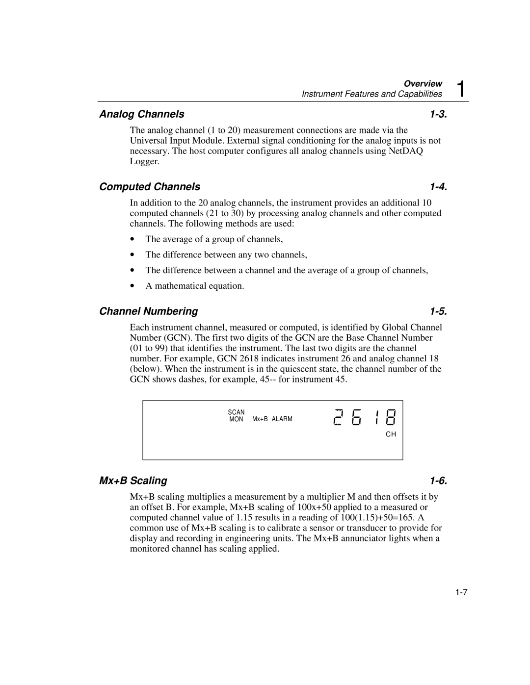
2645A, 2640A specifications
The Fluke 2640A and 2645A are advanced bench multimeters that represent a significant leap in measurement technology, designed primarily for electrical engineers and technicians who require precision and reliability in their readings. These multimeters are built to cater to complex applications in manufacturing, research, and development.One of the standout features of the Fluke 2640A and 2645A is their high accuracy. With specifications that can reach up to 0.0035% DC Voltage accuracy, users can trust that their measurements will be consistent and precise. This is especially critical in fields like automated test equipment (ATE) where exact measurements can be crucial for product quality and safety.
Both models incorporate a large, easy-to-read display, making it convenient for users to view measurement results clearly from a distance. They also feature a wide measurement range, capable of handling a variety of tasks, from basic voltage and current measurements to more complex tasks such as resistance and temperature measurements with appropriate sensors.
The multimeters also stand out with their advanced data logging capabilities. The Fluke 2645A, for instance, can store up to 10,000 readings, allowing for extensive data collection and analysis without the need for constant monitoring. This is beneficial for long-term studies or processes that require continual oversight.
Connectivity is another key characteristic. Both the 2640A and 2645A support USB and RS-232 interfaces, which enable easy integration with computers and other devices for seamless data transfer. This feature is important for engineers who rely on software for data analysis and visualization.
Another notable technology included in these models is the Fluke Connect app compatibility, which allows users to remotely monitor measurements from their smartphones or tablets. This capability provides added flexibility, enabling technicians to work hands-free while still keeping an eye on process measurements.
Additionally, the Fluke 2645A comes with a graphical display option, allowing users to visualize measurement trends over time. This graphical representation can be invaluable for diagnosing issues or observing patterns in data.
In conclusion, the Fluke 2640A and 2645A multimeters offer exceptional performance with their high accuracy, extensive data logging, connectivity options, and advanced visualization capabilities. These features make them indispensable tools for professionals in a variety of fields, ensuring that they can achieve reliable results in their measurement endeavors.

