Fluke 2645A, 2640A user manual Master Alarm, Interval Trigger, External Trigger, Alarm Trigger

Models: 2645A 2640A

1 353
Download 353 pages 43.78 Kb
Page 26
Image 26

2640A/2645A NetDAQ

Users Manual

Master Alarm

1-13.

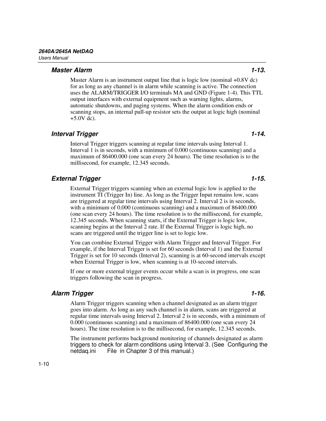
Master Alarm is an instrument output line that is logic low (nominal +0.8V dc) for as long as any channel is in alarm while scanning is active. The connection uses the ALARM/TRIGGER I/O terminals MA and GND (Figure 1-4). This TTL output interfaces with external equipment such as warning lights, alarms, automatic shutdowns, and paging systems. When the alarm condition ends or scanning stops, an internal pull-up resistor sets the output at logic high (nominal +5.0V dc).

Interval Trigger

1-14.

Interval Trigger triggers scanning at regular time intervals using Interval 1. Interval 1 is in seconds, with a minimum of 0.000 (continuous scanning) and a maximum of 86400.000 (one scan every 24 hours). The time resolution is to the millisecond, for example, 12.345 seconds.

External Trigger

1-15.

External Trigger triggers scanning when an external logic low is applied to the instrument TI (Trigger In) line. As long as the Trigger Input remains low, scans are triggered at regular time intervals using Interval 2. Interval 2 is in seconds, with a minimum of 0.000 (continuous scanning) and a maximum of 86400.000 (one scan every 24 hours). The time resolution is to the millisecond, for example, 12.345 seconds. When scanning starts, if the External Trigger is logic low, scanning begins at the Interval 2 rate. If the External Trigger is logic high, no scans are triggered until the trigger line is set to logic low.

You can combine External Trigger with Alarm Trigger and Interval Trigger. For example, if the Interval Trigger is set for 60 seconds (Interval 1) and the External Trigger is set for 10 seconds (Interval 2), scanning is at 60-second intervals except when External Trigger is low, when scanning is at 10-second intervals.

If one or more external trigger events occur while a scan is in progress, one scan triggers following the scan in progress.

Alarm Trigger

1-16.

Alarm Trigger triggers scanning when a channel designated as an alarm trigger goes into alarm. As long as any such channel is in alarm, scans are triggered at regular time intervals using Interval 2. Interval 2 is in seconds, with a minimum of 0.000 (continuous scanning) and a maximum of 86400.000 (one scan every 24 hours). The time resolution is to the millisecond, for example, 12.345 seconds.

The instrument performs background monitoring of channels designated as alarm triggers to check for alarm conditions using Interval 3. (See “Configuring the netdaq.ini File” in Chapter 3 of this manual.)

1-10

Page 26
Image 26
Fluke 2645A, 2640A user manual Master Alarm, Interval Trigger, External Trigger, Alarm Trigger

2645A, 2640A specifications

The Fluke 2640A and 2645A are advanced bench multimeters that represent a significant leap in measurement technology, designed primarily for electrical engineers and technicians who require precision and reliability in their readings. These multimeters are built to cater to complex applications in manufacturing, research, and development.

One of the standout features of the Fluke 2640A and 2645A is their high accuracy. With specifications that can reach up to 0.0035% DC Voltage accuracy, users can trust that their measurements will be consistent and precise. This is especially critical in fields like automated test equipment (ATE) where exact measurements can be crucial for product quality and safety.

Both models incorporate a large, easy-to-read display, making it convenient for users to view measurement results clearly from a distance. They also feature a wide measurement range, capable of handling a variety of tasks, from basic voltage and current measurements to more complex tasks such as resistance and temperature measurements with appropriate sensors.

The multimeters also stand out with their advanced data logging capabilities. The Fluke 2645A, for instance, can store up to 10,000 readings, allowing for extensive data collection and analysis without the need for constant monitoring. This is beneficial for long-term studies or processes that require continual oversight.

Connectivity is another key characteristic. Both the 2640A and 2645A support USB and RS-232 interfaces, which enable easy integration with computers and other devices for seamless data transfer. This feature is important for engineers who rely on software for data analysis and visualization.

Another notable technology included in these models is the Fluke Connect app compatibility, which allows users to remotely monitor measurements from their smartphones or tablets. This capability provides added flexibility, enabling technicians to work hands-free while still keeping an eye on process measurements.

Additionally, the Fluke 2645A comes with a graphical display option, allowing users to visualize measurement trends over time. This graphical representation can be invaluable for diagnosing issues or observing patterns in data.

In conclusion, the Fluke 2640A and 2645A multimeters offer exceptional performance with their high accuracy, extensive data logging, connectivity options, and advanced visualization capabilities. These features make them indispensable tools for professionals in a variety of fields, ensuring that they can achieve reliable results in their measurement endeavors.