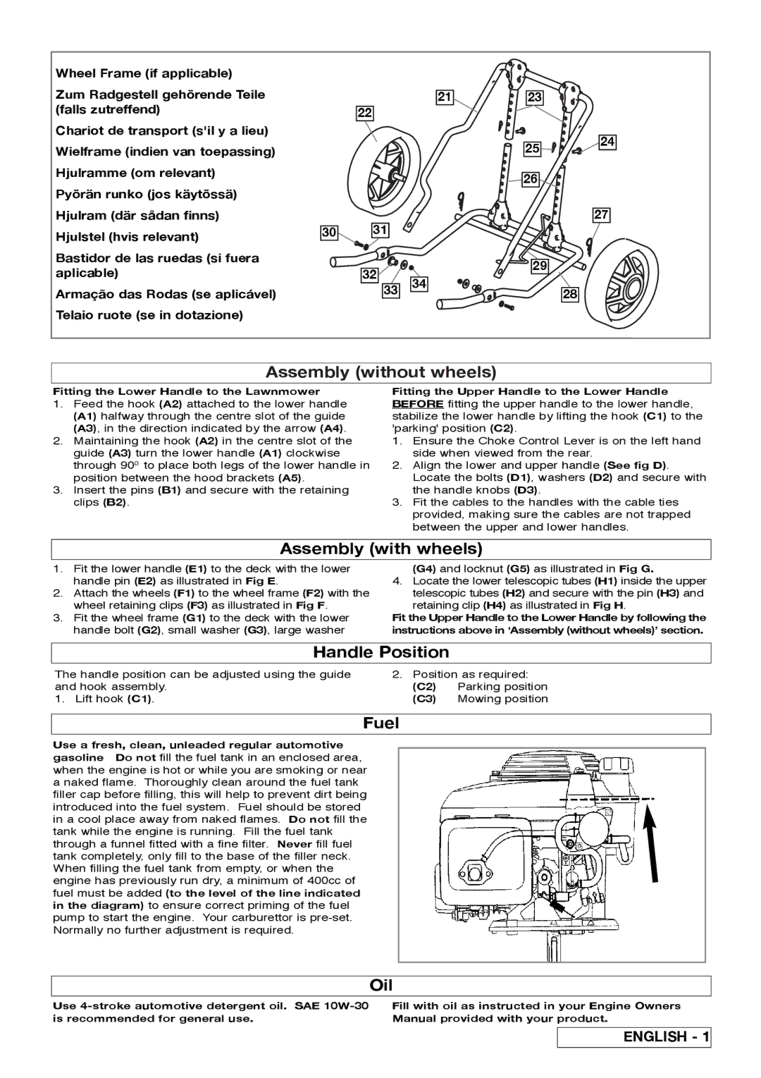
Wheel Frame (if applicable)
Zum Radgestell gehörende Teile (falls zutreffend)
Chariot de transport (s'il y a lieu) Wielframe (indien van toepassing) Hjulramme (om relevant)
Pyörän runko (jos käytössä) Hjulram (där sådan finns) Hjulstel (hvis relevant)
Bastidor de las ruedas (si fuera aplicable)
Armação das Rodas (se aplicável) Telaio ruote (se in dotazione)
30
22
31
32![]()
![]()
![]() 33
33
21
34
23
25![]()
![]()
![]() 24
24
![]()
![]() 26
26
27
29
28
Assembly (without wheels)
Fitting the Lower Handle to the Lawnmower
1.Feed the hook (A2) attached to the lower handle (A1) halfway through the centre slot of the guide
(A3), in the direction indicated by the arrow (A4).
2.Maintaining the hook (A2) in the centre slot of the guide (A3) turn the lower handle (A1) clockwise
through 900 to place both legs of the lower handle in position between the hood brackets (A5).
3.Insert the pins (B1) and secure with the retaining clips (B2).
Fitting the Upper Handle to the Lower Handle BEFORE fitting the upper handle to the lower handle,
stabilize the lower handle by lifting the hook (C1) to the 'parking' position (C2).
1.Ensure the Choke Control Lever is on the left hand side when viewed from the rear.
2.Align the lower and upper handle (See fig D). Locate the bolts (D1), washers (D2) and secure with the handle knobs (D3).
3.Fit the cables to the handles with the cable ties provided, making sure the cables are not trapped between the upper and lower handles.
Assembly (with wheels)
1.Fit the lower handle (E1) to the deck with the lower handle pin (E2) as illustrated in Fig E.
2.Attach the wheels (F1) to the wheel frame (F2) with the wheel retaining clips (F3) as illustrated in Fig F.
3.Fit the wheel frame (G1) to the deck with the lower handle bolt (G2), small washer (G3), large washer
(G4) and locknut (G5) as illustrated in Fig G.
4.Locate the lower telescopic tubes (H1) inside the upper telescopic tubes (H2) and secure with the pin (H3) and
retaining clip (H4) as illustrated in Fig H.
Fit the Upper Handle to the Lower Handle by following the instructions above in ‘Assembly (without wheels)’ section.
Handle Position |
| |
The handle position can be adjusted using the guide | 2. Position as required: | |
and hook assembly. | (C2) | Parking position |
1. Lift hook (C1). | (C3) | Mowing position |
Fuel
Use a fresh, clean, unleaded regular automotive gasoline Do not fill the fuel tank in an enclosed area,
when the engine is hot or while you are smoking or near a naked flame. Thoroughly clean around the fuel tank filler cap before filling, this will help to prevent dirt being introduced into the fuel system. Fuel should be stored in a cool place away from naked flames. Do not fill the
tank while the engine is running. Fill the fuel tank through a funnel fitted with a fine filter. Never fill fuel
tank completely, only fill to the base of the filler neck. When filling the fuel tank from empty, or when the
engine has previously run dry, a minimum of 400cc of fuel must be added (to the level of the line indicated in the diagram) to ensure correct priming of the fuel
pump to start the engine. Your carburettor is
Oil
Use
Fill with oil as instructed in your Engine Owners Manual provided with your product.
ENGLISH - 1