D824/D1624 Quick Operation Guide 

Connecting a digital mixer
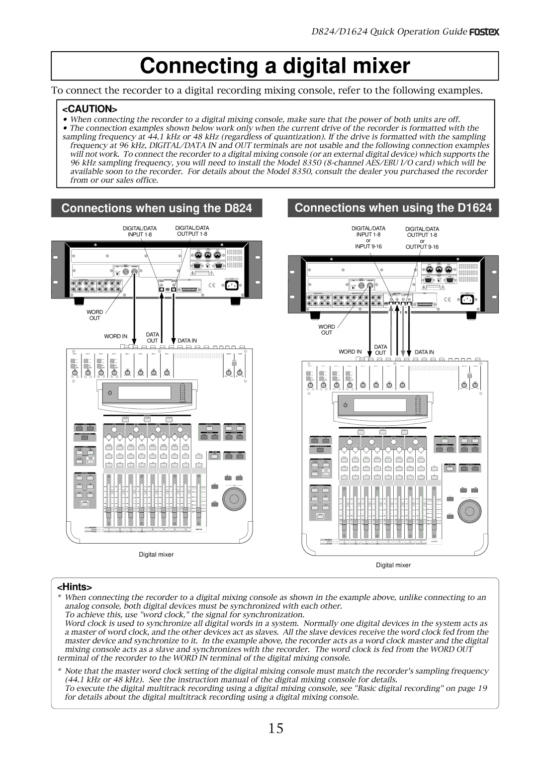
To connect the recorder to a digital recording mixing console, refer to the following examples.
<CAUTION>
•When connecting the recorder to a digital mixing console, make sure that the power of both units are off.
•The connection examples shown below work only when the current drive of the recorder is formatted with the sampling frequency at 44.1 kHz or 48 kHz (regardless of quantization). If the drive is formatted with the sampling
frequency at 96 kHz, DIGITAL/DATA IN and OUT terminals are not usable and the following connection examples will not work. To connect the recorder to a digital mixing console (or an external digital device) which supports the 96 kHz sampling frequency, you will need to install the Model 8350
Connections when using the D824
DIGITAL/DATA | DIGITAL/DATA |
|
| ||||||
INPUT |
| OUTPUT |
|
| |||||
|
|
|
|
|
|
|
|
|
|
|
|
|
|
|
|
|
|
|
|
|
|
|
|
|
|
|
|
|
|
|
|
|
|
|
|
|
|
|
|
|
|
|
|
|
|
|
|
|
|
|
|
|
|
|
|
|
|
|
|
|
|
|
|
|
|
|
|
|
|
|
|
|
|
|
|
|
|
|
|
WORD
OUT
WORD IN | DATA |
| |
OUT | DATA IN | ||
|
Connections when using the D1624
|
|
|
|
|
|
|
|
| DIGITAL/DATA |
|
|
|
|
|
| DIGITAL/DATA | ||||||||||||||||||||||
|
|
|
|
|
|
|
|
|
| INPUT |
|
|
|
|
|
|
|
| OUTPUT | |||||||||||||||||||
|
|
|
|
|
|
|
|
|
|
|
| or |
|
|
|
|
|
|
|
|
|
|
|
|
|
| or | |||||||||||
|
|
|
|
|
|
|
|
| INPUT |
|
|
|
|
|
|
| OUTPUT | |||||||||||||||||||||
|
|
|
|
|
|
|
|
|
|
|
|
|
|
|
|
|
|
|
|
|
|
|
|
|
|
|
|
|
|
|
|
|
|
|
|
|
|
|
|
|
|
|
|
|
|
|
|
|
|
|
|
|
|
|
|
|
|
|
|
|
|
|
|
|
|
|
|
|
|
|
|
|
|
|
|
|
|
|
|
|
|
|
|
|
|
|
|
|
|
|
|
|
|
|
|
|
|
|
|
|
|
|
|
|
|
|
|
|
|
|
|
|
|
|
|
|
|
|
|
|
|
|
|
|
|
|
|
|
|
|
|
|
|
|
|
|
|
|
|
|
|
|
|
|
|
|
|
|
|
|
|
|
|
|
|
|
|
|
|
|
|
|
|
|
|
|
|
|
|
|
|
|
|
|
|
|
|
|
|
|
|
|
|
|
|
|
|
|
|
|
|
|
|
|
|
|
|
|
|
|
|
|
|
|
|
|
|
|
|
|
|
|
|
|
|
|
|
|
|
|
|
|
|
|
|
|
|
|
|
|
|
|
|
|
|
|
|
|
|
|
|
|
|
|
|
|
|
|
|
|
|
|
|
|
|
|
|
|
|
|
|
|
|
|
|
|
|
|
|
|
|
|
|
|
|
|
|
|
|
|
|
|
|
|
|
|
|
|
|
|
|
|
|
|
|
|
|
|
|
|
|
|
|
|
|
|
|
|
|
|
|
|
|
|
|
|
|
|
|
|
|
|
|
|
|
|
|
|
|
|
|
|
|
|
|
|
|
|
|
|
|
|
|
|
|
|
|
|
|
|
WORD
OUT
WORD IN | DATA | DATA IN |
OUT |
INPUT 1 | INPUT 2 | INPUT 3 | INPUT 4 |
|
| INPUT 5 |
| INPUT 6 |
| INPUT 7 |
| INPUT 8 | |||
| A |
| A |
| A |
| A |
|
|
|
|
|
|
|
|
| B |
| B |
| B |
| B |
|
|
|
|
|
|
|
|
| PAD |
| PAD |
| PAD | PAD |
|
|
|
|
|
|
|
| |
| 26dB |
| 26dB |
| 26dB | 26dB |
|
|
|
|
|
|
|
| |
| TRIM |
| TRIM |
| TRIM | TRIM |
|
| TRIM |
| TRIM |
| TRIM |
| TRIM |
+10 | +10 | +10 | +10 |
|
|
|
|
|
|
|
| ||||
| METER |
| OL |
| |
| |
| |
| |
| |
| |
| |
| |
L | R |
ST BUSS/SOLO
| PAGE SELECT |
|
MONITORPHONES
| 2TRK IN |
| |
| GAIN |
| GAIN |
MIN | MAX | MIN | MAX |
INPUT 1 | INPUT 2 | INPUT 3 | INPUT 4 |
|
| INPUT 5 |
| INPUT 6 |
| INPUT 7 |
| INPUT 8 | |||
| A |
| A |
| A |
| A |
|
|
|
|
|
|
|
|
| B |
| B |
| B |
| B |
|
|
|
|
|
|
|
|
| PAD |
| PAD |
| PAD | PAD |
|
|
|
|
|
|
|
| |
| 26dB |
| 26dB |
| 26dB | 26dB |
|
|
|
|
|
|
|
| |
| TRIM |
| TRIM |
| TRIM | TRIM |
|
| TRIM |
| TRIM |
| TRIM |
| TRIM |
+10 | +10 | +10 | +10 |
|
|
|
|
|
|
|
| ||||
| METER |
| OL |
| |
| |
| |
| |
| |
| |
| |
| |
L | R |
ST BUSS/SOLO
MONITORPHONES
| 2TRK IN |
| |
| GAIN |
| GAIN |
MIN | MAX | MIN | MAX |
SETUP
SYSTEMMIDI
CURRENT SCENE STATUS
| EQ/LO |
|
|
| SELECTED EQ |
| |||
| GAIN |
| GAIN |
| GAIN |
| GAIN | EQ ON |
|
|
|
| Q |
| Q |
|
| EQ LIBRARY |
|
FREQ | Q | FREQ | FREQ | FREQ | Q | RECALL | STORE |
| EFF EDIT |
EFF 1 | EFF 2 |
EFF LIBRARY
RECALLSTORE
| PAGE SELECT |
|
| KEY MODE |
ROUTING/ | PAIR/ |
PHASE | GROUP |
| MMC SEND |
CH VIEW | CHANNEL/ |
PAN |
| PAN |
| PAN |
| PAN |
| PAN |
| PAN |
| PAN |
| PAN |
|
|
|
|
|
|
|
|
|
|
|
|
|
|
|
|
|
|
|
EQ EDIT |
| EQ EDIT |
| EQ EDIT |
| EQ EDIT |
| EQ EDIT |
| EQ EDIT |
| EQ EDIT |
| EQ EDIT |
|
|
|
|
|
|
|
|
|
|
|
|
|
|
|
|
|
| REC BUSS |
SOLO |
| SOLO |
| SOLO |
| SOLO |
| SOLO |
| SOLO |
| SOLO |
| SOLO | SOLO | SOLO |
SCENE MEMORY
RECALLSTORE
SETUP
SYSTEMMIDI
CURRENT SCENE STATUS
| EQ/LO |
|
|
| SELECTED EQ |
| |||
| GAIN |
| GAIN |
| GAIN | GAIN |
| EQ ON |
|
|
|
| Q |
| Q |
|
| EQ LIBRARY |
|
FREQ | Q | FREQ | FREQ | FREQ | Q | RECALL | STORE | ||
PAN | PAN | PAN | PAN | PAN | PAN | PAN | PAN |
|
|
EQ EDIT | EQ EDIT | EQ EDIT | EQ EDIT | EQ EDIT | EQ EDIT | EQ EDIT | EQ EDIT |
|
|
| EFF EDIT |
EFF 1 | EFF 2 |
EFF LIBRARY
RECALLSTORE
| METER |
| FADER MODE |
AUX1 | AUX2 |
AUX3 | AUX4 |
| ADD.AUX |
EFF1 | EFF2 |
| CHANNEL |
ANALOG IN
ADAT IN
EFF RTN
ON | ON | ON | ON | ON | ON | ON | ON | ON |
|
|
|
|
|
|
|
|
|
|
|
|
|
|
|
|
|
|
|
|
|
|
|
|
|
|
| EXIT |
+10 | +10 | +10 | +10 | +10 | +10 | +10 | +10 | 0 |
|
0 | 0 | 0 | 0 | 0 | 0 | 0 | 0 |
| |
| |||||||||
|
|
|
|
|
|
|
| ENTER | |
|
| ||||||||
|
|
|
|
|
|
|
|
| |
|
| ||||||||
| |||||||||
- | - | - | - | - | - | - | - | - |
|
1 | 2 | 3 | 4 | 5 | 6 | 7 | 8 |
|
|
9 | 10 | 11 | 12 | 13 | 14 | 15 | 16 |
| MASTER |
17 | 18 | 19 | 20 |
|
|
|
|
|
|
DATA
KEY MODE |
|
ROUTING/ | PAIR/ |
PHASE | GROUP |
MMC SEND |
|
CH VIEW | CHANNEL/ |
METER | |
FADER MODE |
|
AUX1 | AUX2 |
AUX3 | AUX4 |
ADD.AUX |
|
EFF1 | EFF2 |
CHANNEL |
|
ANALOG IN
ADAT IN
EFF RTN
SOLO | SOLO | SOLO | SOLO | SOLO | SOLO | SOLO | SOLO | SOLO |
ON | ON | ON | ON | ON | ON | ON | ON | ON |
+10 | +10 | +10 | +10 | +10 | +10 | +10 | +10 | 0 |
0 | 0 | 0 | 0 | 0 | 0 | 0 | 0 | |
|
|
|
|
|
|
|
| |
| ||||||||
|
|
|
|
|
|
|
| |
| ||||||||
- | - | - | - | - | - | - | - | - |
1 | 2 | 3 | 4 | 5 | 6 | 7 | 8 |
|
9 | 10 | 11 | 12 | 13 | 14 | 15 | 16 | MASTER |
17 | 18 | 19 | 20 |
|
|
|
|
|
REC BUSS
SOLO
EXIT
ENTER
SCENE MEMORY
RECALLSTORE
DATA
Digital mixer
Digital mixer
<Hints>
*When connecting the recorder to a digital mixing console as shown in the example above, unlike connecting to an analog console, both digital devices must be synchronized with each other.
To achieve this, use "word clock," the signal for synchronization.
Word clock is used to synchronize all digital words in a system. Normally one digital devices in the system acts as a master of word clock, and the other devices act as slaves. All the slave devices receive the word clock fed from the master device and synchronize to it. In the example above, the recorder acts as a word clock master and the digital
mixing console acts as a slave and synchronizes with the recorder. The word clock is fed from the WORD OUT terminal of the recorder to the WORD IN terminal of the digital mixing console.
*Note that the master word clock setting of the digital mixing console must match the recorder's sampling frequency (44.1 kHz or 48 kHz). See the instruction manual of the digital mixing console for details.
To execute the digital multitrack recording using a digital mixing console, see "Basic digital recording" on page 19 for details about the digital multitrack recording using a digital mixing console.
15