VM04 Owner’s manual
Before and after the FADER, there are two lines pointing downwards and to the right. These are the selector switches. In the diagram the line after the FADER has an arrow touching it. The line before the FADER is labeled PRE. The line after the FADER is labeled POST. With these switches, you can decide whether to send the audio signal to the internal EFFECT either before or after the FADER. If you choose “PRE”, the audio will be sent to the EFFECT even if you turn down the FADER. As a result only the Effect sound will go out via the STEREO OUT without the dry source sound (i.e., the original raw sound, vocal or instrumental). If you choose “POST”, the INPUT FADER will control the entire audio level including the Effect sound. The VM04 does not have dedicated switches for this purpose, but you select it by entering the CHANNEL EDIT mode.
If you look at the second line after the FADER, you will see that the base of arrow touching it is connected to the EFFECT SEND volume control. This control adjusts the audio level to be sent to the EFFECT in each channel. This control is not available on the VM04 control panel, but you can set it by entering the CHANNEL EDIT mode.
The final part of the INPUT section is labeled “PAN”. With this control, you can individually allocate the audio signal to either the left or the right of the stereo, e.g., the keyboard will be in the right while the guitar will be in the left. The PAN control is also not available on the VM04 control panel. But you can set it by entering the CHANNEL EDIT mode.
We said that the channel 2 input is exactly the same as the channel 1. So what about channels 3 and 4? They have the same structure as Channels 1 and 2 except the TRIM part has been deleted. INPUTs 3 and 4 are labeled
2. Buss Section
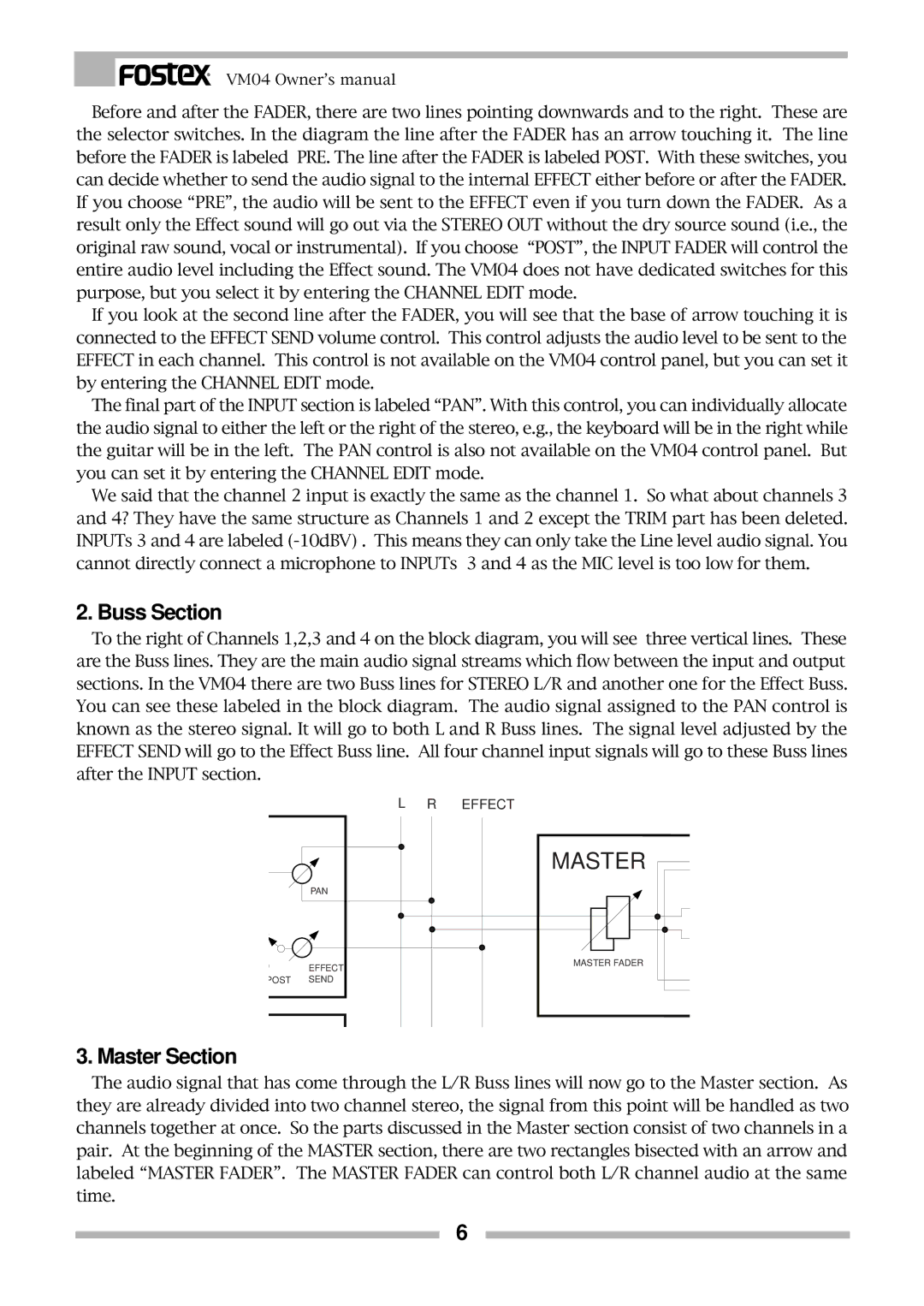
To the right of Channels 1,2,3 and 4 on the block diagram, you will see three vertical lines. These are the Buss lines. They are the main audio signal streams which flow between the input and output sections. In the VM04 there are two Buss lines for STEREO L/R and another one for the Effect Buss. You can see these labeled in the block diagram. The audio signal assigned to the PAN control is known as the stereo signal. It will go to both L and R Buss lines. The signal level adjusted by the EFFECT SEND will go to the Effect Buss line. All four channel input signals will go to these Buss lines after the INPUT section.
L R EFFECT
PAN
EFFECT
POST SEND
MASTER
MASTER FADER
3. Master Section
The audio signal that has come through the L/R Buss lines will now go to the Master section. As they are already divided into two channel stereo, the signal from this point will be handled as two channels together at once. So the parts discussed in the Master section consist of two channels in a pair. At the beginning of the MASTER section, there are two rectangles bisected with an arrow and labeled “MASTER FADER”. The MASTER FADER can control both L/R channel audio at the same time.
6
