Emergency Heat Switch (Defrost Thermostat) Continuity Check
Electric Heat Switch Operation
(Heat Pumps Only)
The electric heat switch is a dual function control and is shown on the wiring diagram as a defrost thermostat. It may be adjusted using a screwdriver. As the control shaft is rotated counter clockwise a detent will be encountered. Turning the control past the detent will lock out the compressor and acts as an emergency heat switch. Turning the control shaft clockwise will lower the change over point for compressor operation. The control it self is a double throw, single pole switch operated by a bellows and a gas fi lled capillary tube. The capillary tube senses a combination of outdoor coil temperature and outdoor air temperature. As the combined temperatures reach a point that the outdoor coil is iced, where heat pump operation is no longer efficient, the control shuts off the compressor and turns on the electric heat. At its lowest setting the cut off point is approximately 25 degrees, the highest setting is 52 degrees, with a 10 degree differential. It is possible, under certain conditions, for the unit to cycle between compressor and electric heat operation.
Electric Heat Switch Check Out
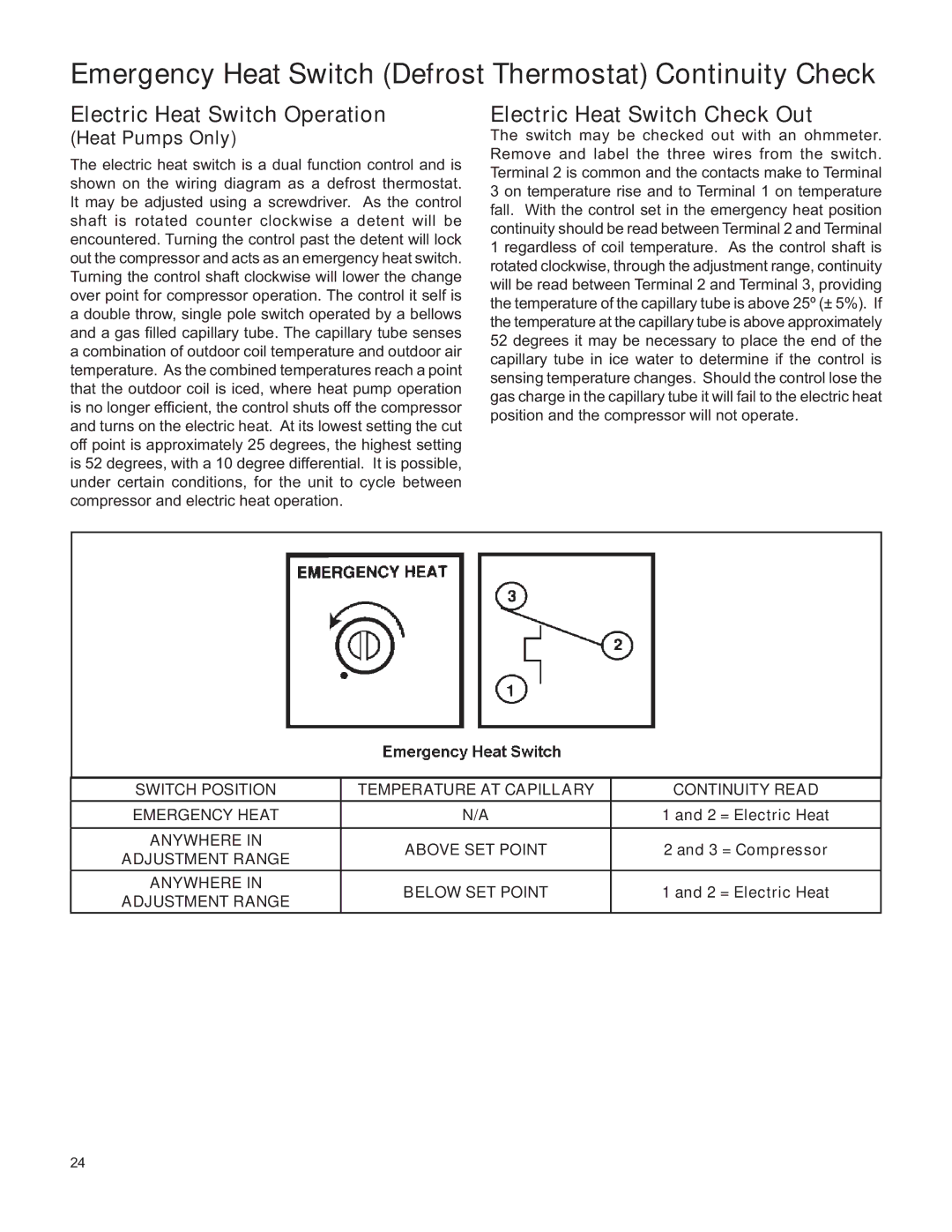
The switch may be checked out with an ohmmeter. Remove and label the three wires from the switch. Terminal 2 is common and the contacts make to Terminal 3 on temperature rise and to Terminal 1 on temperature fall. With the control set in the emergency heat position continuity should be read between Terminal 2 and Terminal 1 regardless of coil temperature. As the control shaft is rotated clockwise, through the adjustment range, continuity will be read between Terminal 2 and Terminal 3, providing the temperature of the capillary tube is above 25º (± 5%). If the temperature at the capillary tube is above approximately 52 degrees it may be necessary to place the end of the capillary tube in ice water to determine if the control is sensing temperature changes. Should the control lose the gas charge in the capillary tube it will fail to the electric heat position and the compressor will not operate.
|
|
| |
SWITCH POSITION | TEMPERATURE AT CAPILLARY | CONTINUITY READ | |
EMERGENCY HEAT | N/A | 1 and 2 = Electric Heat | |
ANYWHERE IN | ABOVE SET POINT | 2 and 3 = Compressor | |
ADJUSTMENT RANGE | |||
|
| ||
ANYWHERE IN | BELOW SET POINT | 1 and 2 = Electric Heat | |
ADJUSTMENT RANGE | |||
|
|
24