Metering Device - Capillary Tube Systems
All units are equipped with capillary tube metering devices.
Checking for restricted capillary tubes.
1.Connect pressure gauges to unit.
2.Start the unit in the cooling mode. If after a few minutes of operation the pressures are normal, the check valve and the cooling capillary are not restricted.
3.Switch the unit to the heating mode and observe the gauge readings after a few minutes running time. If the system pressure is lower than normal, the heating capillary is restricted.
4.If the operating pressures are lower than normal in both the heating and cooling mode, the cooling capillary is restricted.
Reversing Valve Description/Operation
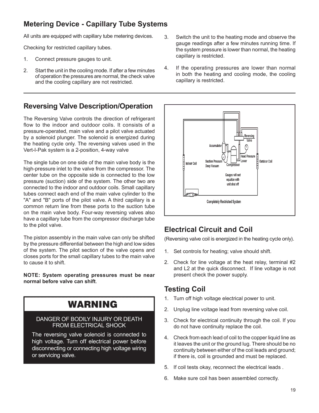
The Reversing Valve controls the direction of refrigerant flow to the indoor and outdoor coils. It consists of a
The single tube on one side of the main valve body is the
The piston assembly in the main valve can only be shifted by the pressure differential between the high and low sides of the system. The pilot section of the valve opens and closes ports for the small capillary tubes to the main valve to cause it to shift.
NOTE: System operating pressures must be near normal before valve can shift.
WARNING
DANGER OF BODILY INJURY OR DEATH
FROM ELECTRICAL SHOCK
The reversing valve solenoid is connected to high voltage. Turn off electrical power before disconnecting or connecting high voltage wiring or servicing valve.
Electrical Circuit and Coil
(Reversing valve coil is energized in the heating cycle only).
1.Set controls for heating; valve should shift.
2.Check for line voltage at the heat relay, terminal #2 and L2 at the quick disconnect. If line voltage is not present check the power supply.
Testing Coil
1.Turn off high voltage electrical power to unit.
2.Unplug line voltage lead from reversing valve coil.
3.Check for electrical continuity through the coil. If you do not have continuity replace the coil.
4.Check from each lead of coil to the copper liquid line as it leaves the unit or the ground lug. There should be no continuity between either of the coil leads and ground; if there is, coil is grounded and must be replaced.
5.If coil tests okay, reconnect the electrical leads .
6.Make sure coil has been assembled correctly.
19