Standard Sash Window Installations
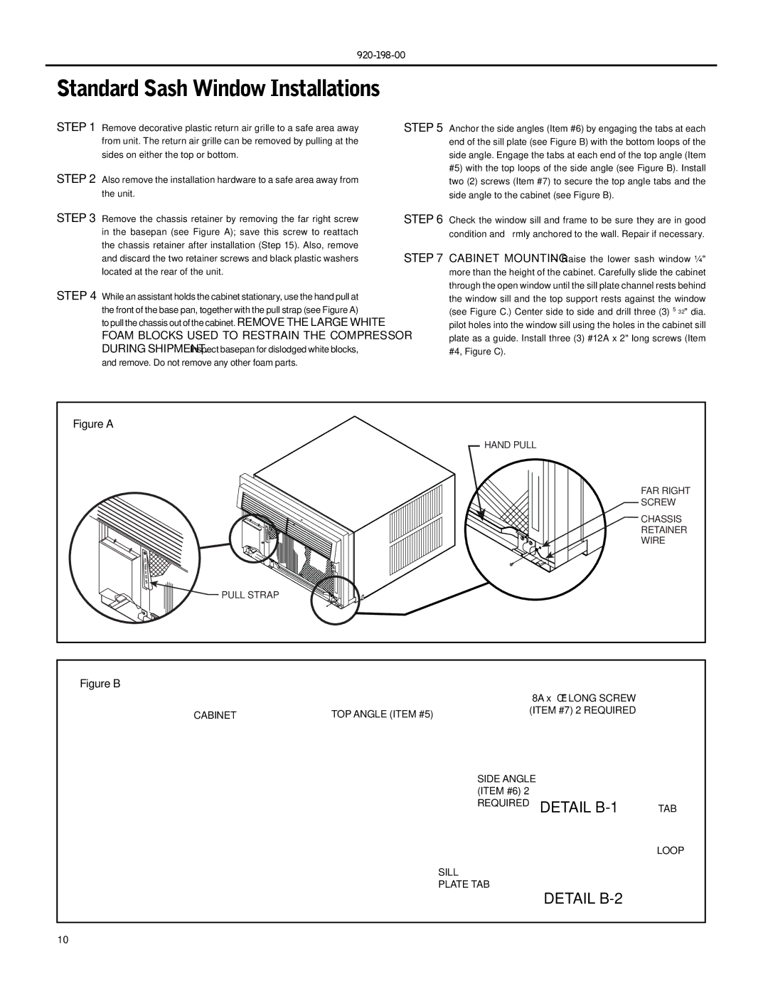
STEP 1 | Remove decorative plastic return air grille to a safe area away | STEP 5 Anchor the side angles (Item #6) by engaging the tabs at each |
| from unit. The return air grille can be removed by pulling at the | end of the sill plate (see Figure B) with the bottom loops of the |
| sides on either the top or bottom. | side angle. Engage the tabs at each end of the top angle (Item |
STEP 2 | Also remove the installation hardware to a safe area away from | #5) with the top loops of the side angle (see Figure B). Install |
two (2) screws (Item #7) to secure the top angle tabs and the | ||
| the unit. | side angle to the cabinet (see Figure B). |
STEP 3 | Remove the chassis retainer by removing the far right screw | STEP 6 Check the window sill and frame to be sure they are in good |
| in the basepan (see Figure A); save this screw to reattach | condition and firmly anchored to the wall. Repair if necessary. |
| the chassis retainer after installation (Step 15). Also, remove | STEP 7 CABINET MOUNTING – Raise the lower sash window ¼" |
| and discard the two retainer screws and black plastic washers | |
| located at the rear of the unit. | more than the height of the cabinet. Carefully slide the cabinet |
STEP 4 | While an assistant holds the cabinet stationary, use the hand pull at | through the open window until the sill plate channel rests behind |
the window sill and the top support rests against the window | ||
| the front of the base pan, together with the pull strap (see Figure A) | (see Figure C.) Center side to side and drill three (3) 5⁄ 32" dia. |
| to pull the chassis out of the cabinet. REMOVE THE LARGE WHITE | pilot holes into the window sill using the holes in the cabinet sill |
| FOAM BLOCKS USED TO RESTRAIN THE COMPRESSOR | plate as a guide. Install three (3) #12A x 2" long screws (Item |
| DURING SHIPMENT. Inspect basepan for dislodged white blocks, | #4, Figure C). |
| and remove. Do not remove any other foam parts. |
|
Figure A |
HAND PULL |
FAR RIGHT |
SCREW |
CHASSIS |
RETAINER |
WIRE |
PULL STRAP |
Figure B
|
| 8A x ⅜" LONG SCREW |
CABINET | TOP ANGLE (ITEM #5) | (ITEM #7) 2 REQUIRED |
|
SIDE ANGLE |
| |
(ITEM #6) 2 |
|
|
REQUIRED | DETAIL | TAB |
LOOP
SILL
PLATE TAB
DETAIL B-2
10