Setting Surface Controls

Sizes of the Surface Gas Burners

Your appliance is supplied with 4 different surface gas burners:

1 Simmer Burner (5,000 BTU)

1 Standard Burner (9,500 BTU)

1 Power Burner (12,000 BTU)

1 Power Burner (14,000 BTU)

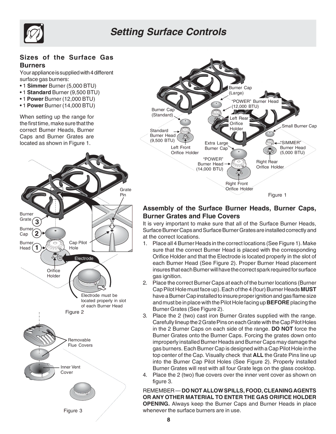
When setting up the range for the first time, make sure that the correct Burner Heads, Burner Caps and Burner Grates are located as shown in Figure 1.

Grate

Pin

Burner


Grate


Burner


Cap


Burner

Cap Pilot

Head

Hole


Electrode


Orifice


Holder

Electrode must be located properly in slot of each Burner Head

Figure 2

Removable

Flue Covers

Inner Vent

Cover

Figure 3

Burner Cap (Large)


“POWER” Burner Head


Burner Cap


(12,000 BTU)


(Standard)


Left Rear


Orifice

Small Burner Cap

Standard


Holder


Burner Head


(9,500 BTU)

Extra Large


“SIMMER”

Left Front


Burner Cap


Burner Head

Orifice Holder


(5,000 BTU)


“POWER”

Right Rear


Burner Head


Orifice Holder


(14,000 BTU)


Right Front

Orifice Holder

Figure 1

Assembly of the Surface Burner Heads, Burner Caps, Burner Grates and Flue Covers

It is very important to make sure that all of the Surface Burner Heads, Surface Burner Caps and Surface Burner Grates are installed correctly and at the correct locations.

1.Place all 4 Burner Heads in the correct locations (See Figure 1). Make sure that the correct Burner Head is placed with the corresponding Orifice Holder and that the Electrode is located properly in the slot of each Burner Head (See Figure 2). Proper Burner Head placement insures that each Burner will have the correct spark required for surface gas ignition.

2.Place the correct Burner Caps at each of the burner locations (Burner Cap Pilot Hole must face up). Each of the 4 (four) Burner Heads MUST have a Burner Cap installed to insure proper ignition and gas flame size and must be in place with the Pilot Hole facing up BEFORE placing the Burner Grates (See Figure 2).

3.Place the 2 (two) cast iron Burner Grates supplied with the range. Carefully lineup the 2 Grate Pins on each Grate with the Cap Pilot Holes in the 2 Burner Caps on each side of the range. DO NOT force the Burner Grates onto the Burner Caps. Forcing the grates down onto improperly installed Burner Heads and Burner Caps may damage the gas burners. Each Burner Cap is designed with a Cap Pilot Hole in the top center of the Cap. Visually check that ALL the Grate Pins line up into the Burner Cap Pilot Holes (See Figure 2). Properly installed Burner Grates will rest with all four Grate legs on the glass cooktop.

4.Place the 2 (two) flue covers over the inner vent cover as shown on figure 3.

REMEMBER — DO NOT ALLOW SPILLS, FOOD, CLEANING AGENTS

OR ANY OTHER MATERIAL TO ENTER THE GAS ORIFICE HOLDER OPENING. Always keep the Burner Caps and Burner Heads in place whenever the surface burners are in use.

8

Page 8
Image 8
Frigidaire 318200879 manual Setting Surface Controls, Sizes of the Surface Gas Burners

318200879 specifications

The Frigidaire 318200879 is a versatile and high-performance replacement part designed to enhance the efficiency and functionality of your cooking experience. As an essential component for various Frigidaire models, it is specifically crafted to ensure reliable performance and seamless integration into your existing appliances. This part is predominantly used in ovens and ranges, catering to a wide audience looking for the right solutions for their kitchen needs.

One of the key features of the Frigidaire 318200879 is its high-grade construction. Made from durable materials, this component is engineered to withstand high temperatures and resist wear over time, ensuring longevity and reliability. This durability not only simplifies maintenance but also offers peace of mind to users who prioritize quality in their kitchen appliances.

The Frigidaire 318200879 embodies advanced technology that supports efficient cooking processes. It is designed to distribute heat evenly, ensuring that food cooks consistently and thoroughly, which is essential for achieving perfect results every time. Additionally, the part is compatible with a range of cooking methods, including baking, broiling, and roasting, providing versatility for various culinary applications.

Installation of the Frigidaire 318200879 is straightforward, making it accessible for both professional technicians and DIY enthusiasts. Its user-friendly design allows for easy replacement without the need for extensive tools or skills, enabling homeowners to restore their cooking appliances quickly and efficiently. This ease of installation significantly reduces downtime, allowing users to return to their culinary projects without major interruptions.

Moreover, this part is designed with safety features in mind. Ensuring proper installation and operation is crucial for preventing potential hazards in the kitchen. The Frigidaire 318200879 integrates safety technologies that help maintain the appliance’s stability and performance, providing users with a reliable and secure cooking environment.

In conclusion, the Frigidaire 318200879 is a standout choice for anyone looking to enhance their kitchen with reliable and efficient technology. With its durable construction, advanced heat distribution capabilities, ease of installation, and integrated safety features, this part stands as a testament to Frigidaire’s commitment to quality and performance in the realm of home cooking.