Manuals
/
Frymaster
/
Kitchen Appliance
/
Fryer
Frymaster
2836
manual
Oil Return Assembly
Models:
2836
1
49
54
54
Download
54 pages
31.84 Kb
46
47
48
49
50
51
52
53
Page 49
Image 49
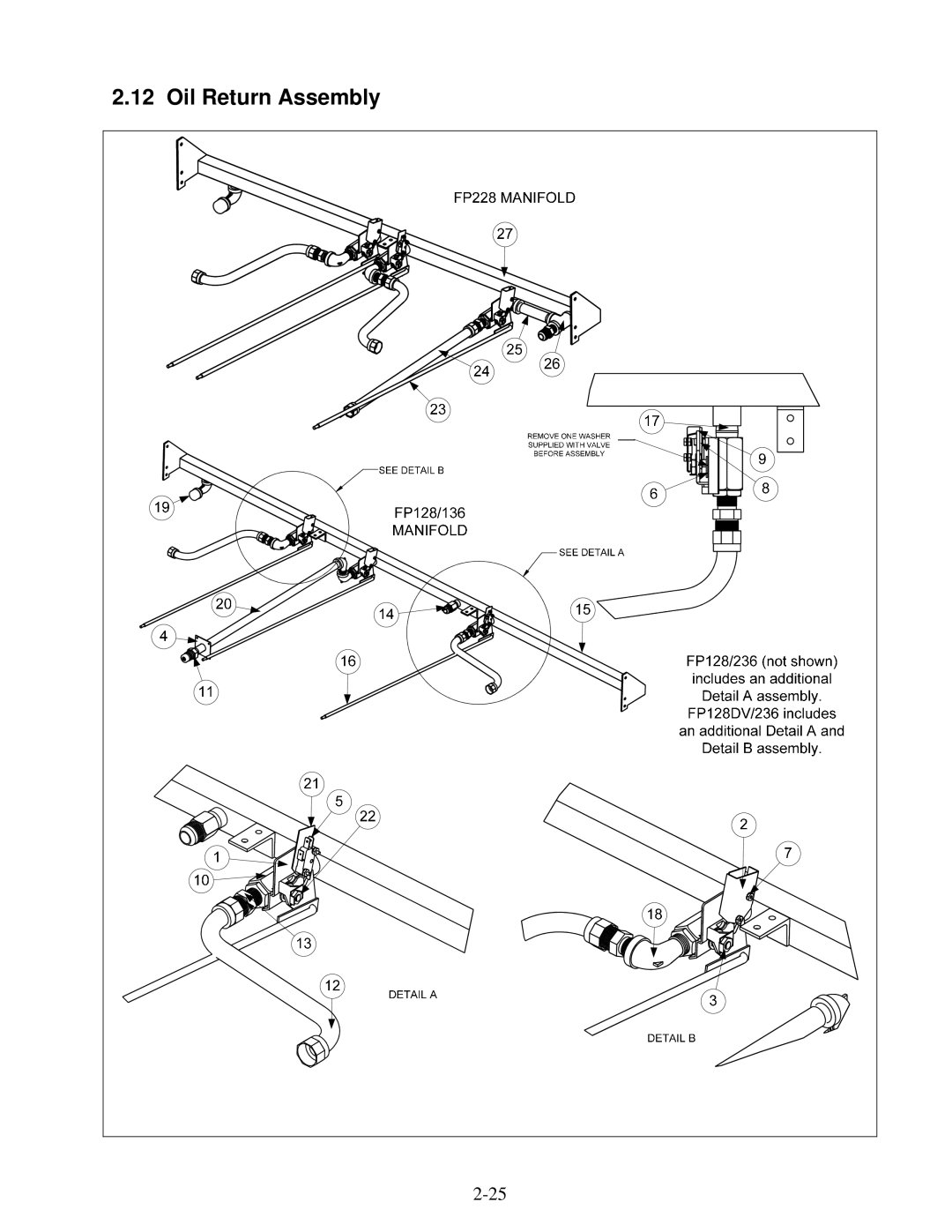
2.12 Oil Return Assembly
2-25
Page 48
Page 50
Page 49
Image 49
Page 48
Page 50
Contents
Hour Service Hotline
Series Electric Fryers Service and Parts Manual
Canada
Page
Table of Contents
Parts List
Contactor Box
Component Box
Replace Computer/Controller
General
Replace Interface Board
Replace Transformer
Replace Temperature Probe
Replace Heating Element
Replacement element. Ensure the pin
Replace Frypot
Replace High-Limit
Replace Contactor Latching or Heating
Built-in Filter System Service Procedures
Sediment Particle Oil Flow Up for reverse Down for forward
Basket Lift Service Procedures
Simplified Schematic
BINDING/JAMMING Problems
Diagnostic LED Legend
Electric Interface Board Diagnostic Chart
Probe Resistance Chart
Probe Resistance Chart
Wiring Diagrams, Main 208/240V
Wiring Diagrams, Main 480V 120 V Controls
Wiring Diagrams, Main FP28DV/36 480V 120 V Controls
Wiring Diagrams, Modular Basket Lifts
Wiring Diagrams 208/240V Systems With Built-in Filtration
Wiring Diagrams 480V Systems With Built-in Filtration
Accessories
Series Electric Fryers Parts List
Basket Lift Assembly Modular and Related Components
Basket Lift Assembly Modular and Related Components
Basket Lift Assembly Modular and Related Components
Page
1.1 FP228 Cabinet and Related Components
1.2 FP128/136 Cabinet and Related Components
1.2 FP128/136 Cabinet and Related Components
1.3 FP128/236 Cabinet and Related Components
Cabinet Assembly FP128/236 use 106-5891 for FP128DV/236S
Door Components
Dump Station Components
Computer and Related Components
Contactor and Power Cord Box Assembly
Part Number
Terminal Block Mount Assembly
Component Box Assembly
Component Box Assembly
Filter Pan and Related Components Built-in Filtration
Handle, Drain Valve Use 230-0892 for FP14 FP28DV
Drain Components
Elements and Related Components
References Previous models
Oil Disposal Wand
Oil Return Assembly
Return Assembly
Filter Pump Assembly
Part Number Description Basket Lift Harnesses
Wiring Harnesses and Cables
This page Intentionally Left Blank
Service Hotline
Top
Page
Image
Contents