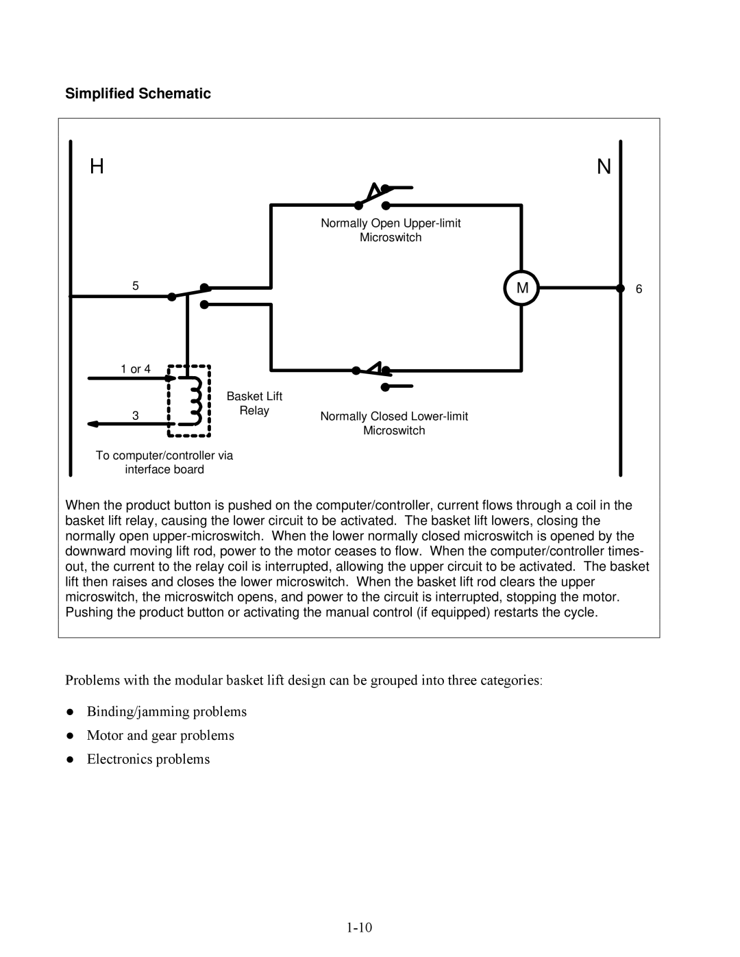
Simplified Schematic
HN
Normally Open Upper-limit
Microswitch
1 or 4 | | |
| Basket Lift | |
3 | Relay | Normally Closed Lower-limit |
|
Microswitch
To computer/controller via
interface board
When the product button is pushed on the computer/controller, current flows through a coil in the basket lift relay, causing the lower circuit to be activated. The basket lift lowers, closing the normally open upper-microswitch. When the lower normally closed microswitch is opened by the downward moving lift rod, power to the motor ceases to flow. When the computer/controller times- out, the current to the relay coil is interrupted, allowing the upper circuit to be activated. The basket lift then raises and closes the lower microswitch. When the basket lift rod clears the upper microswitch, the microswitch opens, and power to the circuit is interrupted, stopping the motor. Pushing the product button or activating the manual control (if equipped) restarts the cycle.
Problems with the modular basket lift design can be grouped into three categories:
●Binding/jamming problems
●Motor and gear problems
●Electronics problems
1-10