4.3 Connection Requirements
4.3Connection Requirements
4.3.1Connector
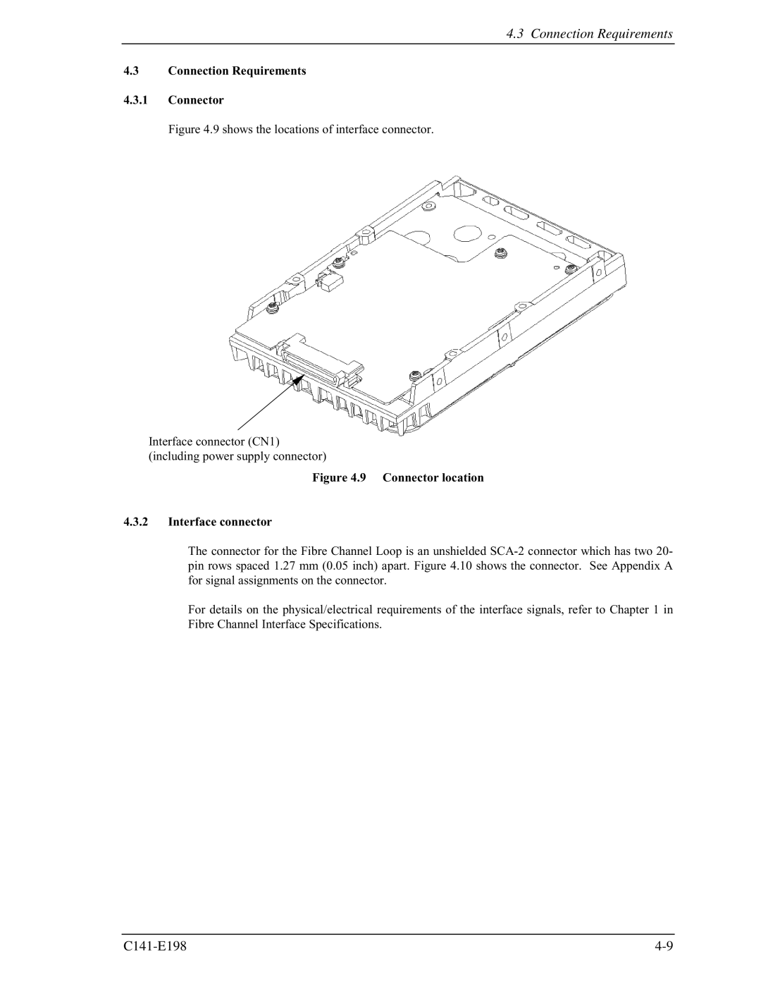
Figure 4.9 shows the locations of interface connector.
Interface connector (CN1) (including power supply connector)
Figure 4.9 Connector location
4.3.2Interface connector
The connector for the Fibre Channel Loop is an unshielded
For details on the physical/electrical requirements of the interface signals, refer to Chapter 1 in Fibre Channel Interface Specifications.