3.1 Data Space
Cylinder skew
Head
Cylinder skew
P
Track skew
Head
P+1
Leading logical sector in head p+1
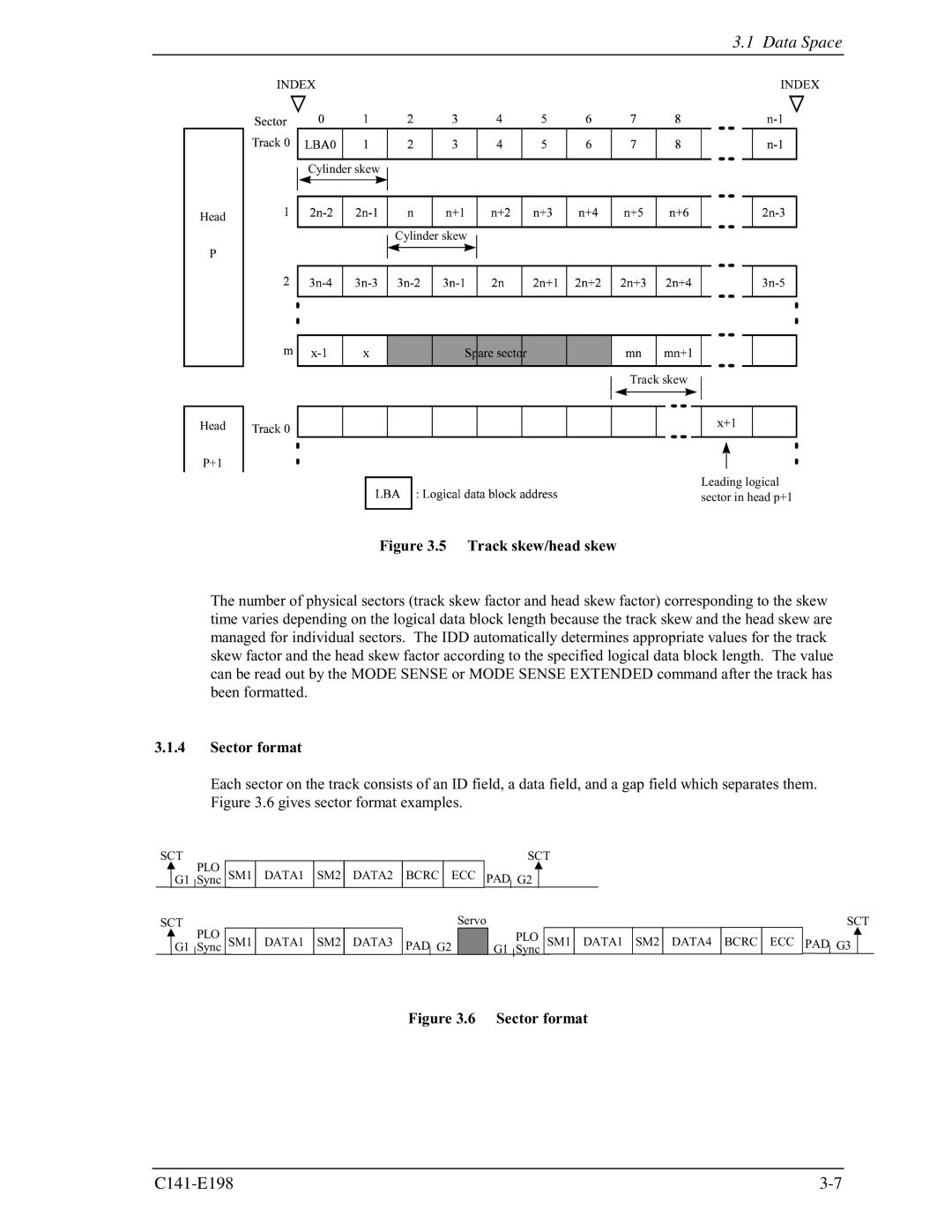
Figure 3.5 Track skew/head skew
The number of physical sectors (track skew factor and head skew factor) corresponding to the skew time varies depending on the logical data block length because the track skew and the head skew are managed for individual sectors. The IDD automatically determines appropriate values for the track skew factor and the head skew factor according to the specified logical data block length. The value can be read out by the MODE SENSE or MODE SENSE EXTENDED command after the track has been formatted.
3.1.4Sector format
Each sector on the track consists of an ID field, a data field, and a gap field which separates them. Figure 3.6 gives sector format examples.
SCT | PLO |
|
|
|
|
|
|
|
|
|
|
|
| SCT |
|
|
| ||||||
| SM1 | DATA1 | SM2 | DATA2 | BCRC |
| ECC | PAD |
|
|
|
|
|
|
|
|
|
|
| ||||
G1 | Sync |
|
| G2 |
|
|
|
|
|
|
|
|
| ||||||||||
|
|
|
|
|
|
|
|
|
| ||||||||||||||
SCT | PLO |
|
|
|
|
|
|
|
| Servo |
|
|
|
|
|
|
| SCT | |||||
| SM1 | DATA1 | SM2 | DATA3 | PAD |
|
|
|
|
|
|
| PLO | SM1 | DATA1 | SM2 | DATA4 | BCRC | ECC | PAD G3 | |||
G1 | Sync |
| G2 |
|
| G1 Sync | |||||||||||||||||
|
|
| |||||||||||||||||||||