MB39A104
2. Control Function
When CTL terminal (pin 24) is “L” level, IC becomes the standby mode. The power supply current is 10 ∝A (Max) at the standby mode.
On/Off Setting Conditions
CTL
L
H
Power
OFF (Standby)
ON (Operating)
3.Protective Functions
(1)Timer-latch overcurrent protection circuit block (OCP)
The
Changing connection enables to detect overcurrent at current sense resistor.
To reset the actuated protection circuit, either the power supply turn off and on again or set the CTL terminal (pin 6) to the “L” level to lower the VREF terminal (pin 17) voltage to 2.4 V (Min) or less. (See “1. Setting Timer- Latch Overcurrent Protection Detection Current” in “ ■ABOUT
(2)
The
When the capacitor voltage reaches about 0.73 V, the circuit is turned off the output transistor and sets the dead time to 100 %.
To reset the actuated protection circuit, either the power supply turn off and on again or set the CTL terminal (pin 24) to the “L” level to lower the VREF terminal (pin 17) voltage to 2.4 V (Min) or less. (See “2. Setting Time Constant for
(3) Under voltage lockout protection circuit (UVLO)
The transient state or a momentary decrease in supply voltage, which occurs when the power supply is turned on, may cause the IC to malfunction, resulting in breakdown or degradation of the system. To prevent such malfunctions, under voltage lockout protection circuit detects a decrease in internal reference voltage with respect to the power supply voltage, turns off the output transistor, and sets the dead time to 100% while holding the CSCP terminal (pin 8) at the “L” level.
The circuit restores the output transistor to normal when the supply voltage reaches the threshold voltage of the undervoltage lockout protection circuit.
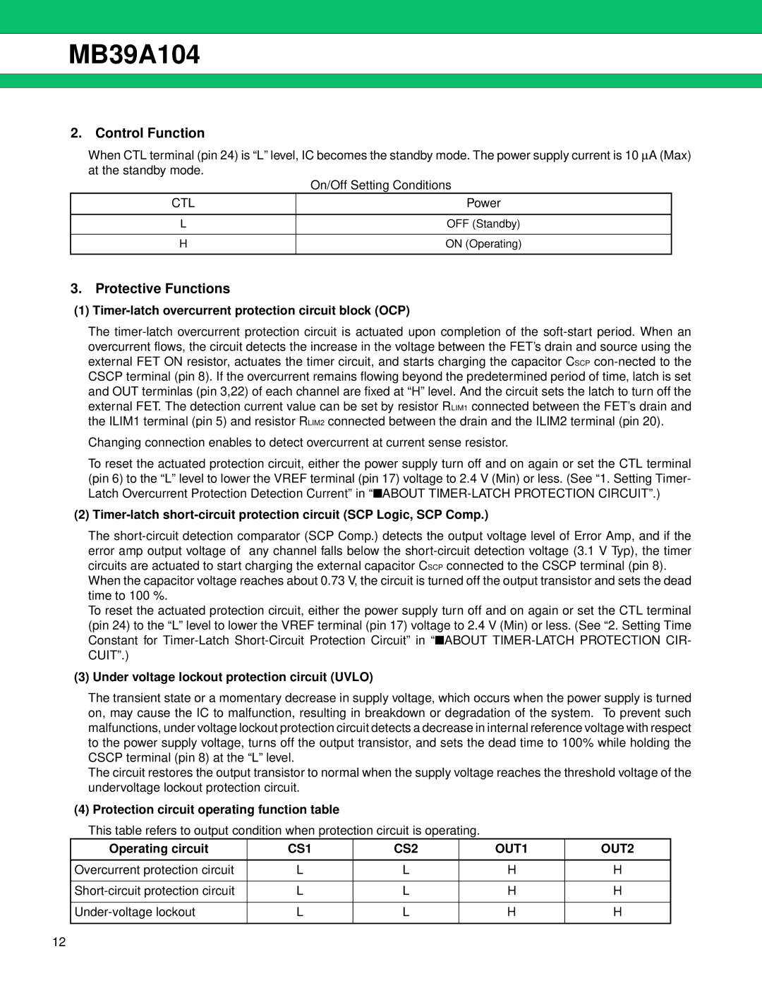
(4) Protection circuit operating function table
This table refers to output condition when protection circuit is operating.
Operating circuit | CS1 | CS2 | OUT1 | OUT2 |
|
|
|
|
|
Overcurrent protection circuit | L | L | H | H |
|
|
|
|
|
L | L | H | H | |
|
|
|
|
|
L | L | H | H | |
|
|
|
|
|
12