MB39A104
■SETTING THE SOFT-START AND DISCHARGE TIMES
To prevent rush currents when the IC is turned on, you can set a soft-start by connecting soft-start capacitors (CS1 and CS2) to the CS1 terminal (pin 11) for channel 1 and the CS2 terminal (pin 14) for channel 2, respectively. When CTL terminal (pin 24) goes to “H” level and IC starts (V CC ≥ UVLO threshold voltage), the external soft- start capacitors (CS1 and CS2) connected to CS1 and CS2 terminals are charged at 10 ∝A. The error amplifier output (FB1 (pin 9) , FB2 (pin 16) ) is determined by comparison between the lower one of the potentials at two non-inverted input terminals (1.24 V, CS1 terminal voltages) and the inverted input terminal voltage (−INE1 (pin 10) voltage, −INE2 (pin 15) voltage).
The FB1 (FB2) terminal voltage is decided for the soft-start period by the comparison between 1.24 V in an internal reference voltage and the voltages of the CS1 (CS2) terminal. The DC/DC converter output voltage rises in proportion to the CS1 (CS2) terminal voltage as the soft-start capacitor connected to the CS1 (CS2) terminal is charged.
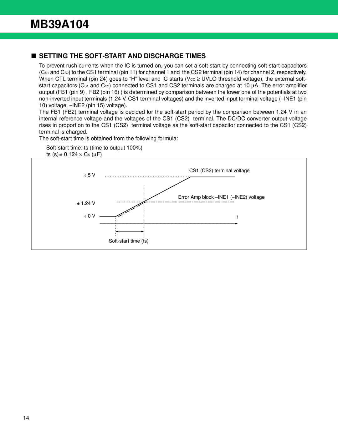
The soft-start time is obtained from the following formula:
Soft-start time: ts (time to output 100%)
ts (s) =: 0.124 ⋅ CS (∝F)
=: 5 | V | | | CS1 (CS2) terminal voltage |
| | | |
| | | | Error Amp block −INE1 (−INE2) voltage |
=: 1.24 | V | | | | |
=: 0 | V | | | | t |
| | | | | |
| | | | | |
Soft-start time (ts)