MB39A104
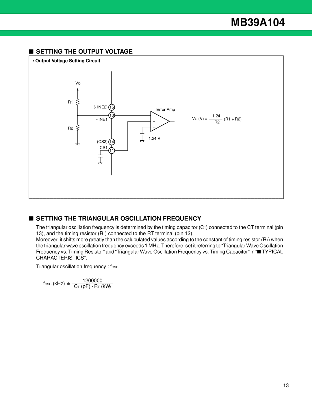
■SETTING THE OUTPUT VOLTAGE
•Output Voltage Setting Circuit
VO
R1
(−INE2) 15
10
−INE1
R2
(CS2) | 14 |
CS1 | 11 |
| Error Amp |
|
|
| ||
− |
|
| VO (V) = | 1.24 | (R1 | + R2) |
+ |
|
|
| |||
|
|
| ||||
|
|
| R2 |
| ||
|
|
|
| |||
|
|
|
|
| ||
+
1.24 V
■SETTING THE TRIANGULAR OSCILLATION FREQUENCY
The triangular oscillation frequency is determined by the timing capacitor (CT) connected to the CT terminal (pin 13), and the timing resistor (RT) connected to the RT terminal (pin 12).
Moreover, it shifts more greatly than the caluculated values according to the constant of timing resistor (RT) when the triangular wave oscillation frequency exceeds 1 MHz. Therefore, set it referring to “Triangular Wave Oscillation Frequency vs. Timing Resistor” and “Triangular Wave Oscillation Frequency vs. Timing Capacitor” in “ ■ TYPICAL CHARACTERISTICS”.
Triangular oscillation frequency : fOSC
1200000
fOSC (kHz) =: CT (pF) •RT (kΩ)
13
