INSTALLATION
•To prevent the plasma display’s internal components from overheating, make sure that the plasma display is installed in a
•Be sure to use the optional stand,
•See the appropriate instruction manual for additional information on the mounting hardware you select.
•To prevent an accident and ensure safety in the event of an earthquake, fix the plasma display securely into the position as described below.
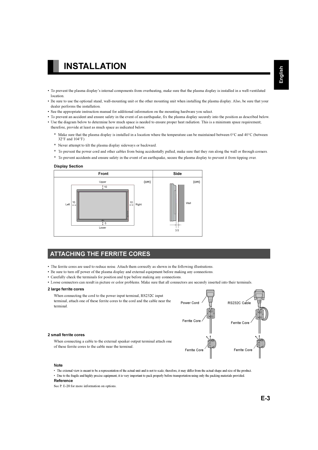
•Use the diagram below to determine how much space is needed to ensure proper heat radiation. This is a minimum space requirement; therefore, provide at least as much space as indicated below.
*Make sure that the plasma display is installed in a location where the temperature can be maintained between 0°C and 40°C (between 32°F and 104°F)
*Never attempt to tilt the plasma display sideways or backward.
*To prevent the power cord and other cables from being accidentally pulled, make sure that they run along the wall or through corners.
*To prevent accidents and ensure safety in the event of an earthquake, secure the plasma display to prevent it from tipping over.
Display Section |
|
|
|
Front |
|
| Side |
Upper |
| (cm) | (cm) |
10 |
|
|
|
10 | 10 | Right | Wall |
Left |
|
| |
5 |
|
|
|
Lower |
|
| 3.5 |
|
|
|
ATTACHING THE FERRITE CORES
•The ferrite cores are used to reduce noise. Attach them correctly as shown in the following illustrations.
•Be sure to turn off power of the plasma display and external equipment before making any connections.
•Carefully check the terminals for position and type before making any connections.
•Loose connectors can result in picture or color problems. Make sure that all connectors are securely inserted into their terminals.
Póññêèé Português Italiano Français Español Deutsch English
2 large ferrite cores
When connecting the cord to the power input terminal, RS232C input terminal, attach one of these ferrite cores to the cord and the cable near the terminal.
Power Cord ![]()
![]() RS232C Cable
RS232C Cable
Ferrite Core | Ferrite Core |
|
2 small ferrite cores
When connecting a cable to the external speaker output terminal attach one of these ferrite cores to the cable near the terminal.
Ferrite Core | Ferrite Core |
Note
•The external view is meant to be a representation of the actual unit and is not to scale; therefore, it may differ from the actual shape and size of the product.
•Due to the fragile and highly precise equipment, it is very important to pack properly before transportation using only the packing materials provided.
Reference
See P.
中文
日 本 語