Model Model
USA
Important Notices
European Union
Other countries
Safety Instructions
Compliance with R&TTE Directive 1999/5/EC
Table of Contents
Foreword
Features
Word to the Owner of the Model
System Configuration
Navigator
Equipment Lists
Antenna installation materials
Display unit installation materials
Standard supply
Controls
How to remove the hard cover
Operation
Display unit
Indications
Indications
About the LCD
Transmitting, Standby
Turning Power On/Off
Brilliance/contrast adjustment window
Startup screen
Choosing the Range
Adjusting Display Contrast, Brilliance
Automatic gain adjustment
Receiver Sensitivity
Manual gain adjustment
Automatic adjustment by the A/C SEA control
Manual adjustment of A/C SEA
Automatic A/C SEA adjustment
Measuring range by the range rings
Suppressing Rain Clutter
Measuring the Range
Measuring range by the cursor
Measuring bearing with the cursor
Measuring the Bearing
Shifting the Display
Measuring bearing with the EBL
Zoom display
Zoom
User Menu Overview
User menu,
User menu description
Heading Line
Interference Rejector
Appearance of interference
Echo Stretch
Noise Rejector
Echo Trail, Trail Brilliance
Echo trails
Silencing the audio alarm
Guard Alarm
Setting a guard zone
Canceling the guard zone and guard alarm
Suppressing Heavy Rain Clutter
Setting watchman stand-by interval
Watchman
Panel Backlighting
Prog Key
Resetting Distance Run
24 Hue
Outputting Target Position to a Plotter
Turning Navigation Data On/Off
Setting up Nav Data Displays
30 00.065N 130 00.574E
30 00.065N
21 nm
Nav data displays
130 00.574E
1 of system menu
System Menu
System menu description
Waypoint Mark The waypoint mark shows
3 of system menu
Maintenance program
MAINTENANCE, Troubleshooting
Maintenance
Period Check point Action
Replacing the Fuse
Troubleshooting
Troubleshooting
If… But… Then…
Display unit
Diagnostics
Installation menu
Antenna unit
Replacing the Magnetron
Test Pattern
Clearing the Memory
Replacing the Synchro Belt
Mounting considerations
Installation
Antenna Unit Installation
Mounting on a platform
Antenna unit, inside view
How to fasten the antenna base to platform
Antenna cable and gasket to use
Contents of radome mounting assy
Mounting using the optional mounting bracket
How to fix the EMI core
Connecting antenna cable to antenna unit
Desktop, overhead mounting
Display Unit Installation
Mounting
Flush mounting
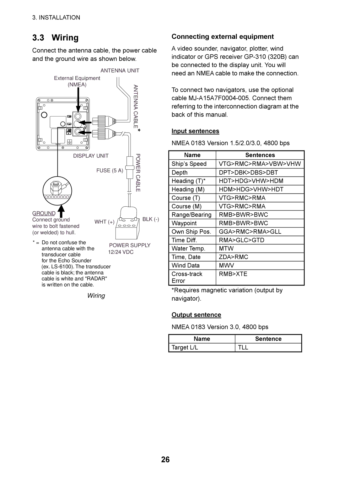
Wiring
Wiring
Connecting external equipment
Input sentences
Heading alignment
Adjustments
Connecting the external buzzer
Display unit, rear view
Timing adjustment
Nmea port setup, GPS Waas setup
Timing adjustment display
Magnetron Heater Voltage
MD board
Menu Tree
Trail Brilliance LOW, High System Menu
Specifications of Marine Radar
SP-1
Environmental Conditions
SP-2
Page
Page
Page
Page
Marine Radar
Page
00014790912