Mounting Considerations, Protection, Hydraulic Connections, Magnetic
Environment, System Maintenance
Pump Unit: The Pump unit will need to be mounted within at least 20” of the ECU. It will need to be mounted in a horizontal position to a solid surface. Do not mount the pump vertical with the pump end down, air gets trapped in the pump head end and it will not work correctly. Do not lengthen or splice the #5 wire or the orange and black power wires. See page 18
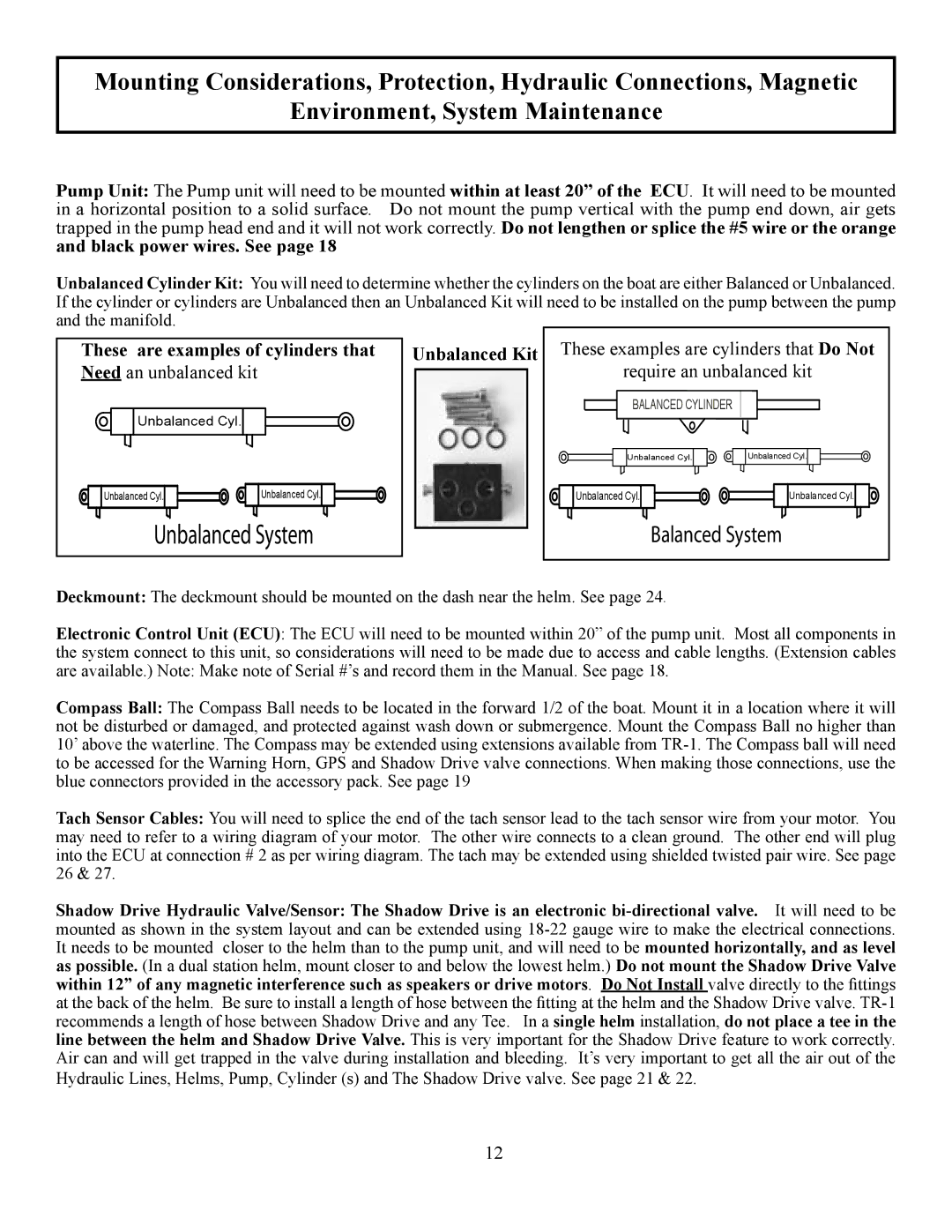
Unbalanced Cylinder Kit: You will need to determine whether the cylinders on the boat are either Balanced or Unbalanced. If the cylinder or cylinders are Unbalanced then an Unbalanced Kit will need to be installed on the pump between the pump and the manifold.
These are examples of cylinders that Need an unbalanced kit
Unbalanced Cyl.
Unbalanced Cyl. | Unbalanced Cyl. |
���������� ������
Unbalanced Kit
These examples are cylinders that Do Not | |
require an unbalanced kit | |
BALANCED CYLINDER |
|
Unbalanced Cyl. | Unbalanced Cyl. |
Unbalanced Cyl. | Unbalanced Cyl. |
�������� ������ | |
Deckmount: The deckmount should be mounted on the dash near the helm. See page 24.
Electronic Control Unit (ECU): The ECU will need to be mounted within 20” of the pump unit. Most all components in the system connect to this unit, so considerations will need to be made due to access and cable lengths. (Extension cables are available.) Note: Make note of Serial #’s and record them in the Manual. See page 18.
Compass Ball: The Compass Ball needs to be located in the forward 1/2 of the boat. Mount it in a location where it will not be disturbed or damaged, and protected against wash down or submergence. Mount the Compass Ball no higher than 10’ above the waterline. The Compass may be extended using extensions available from
Tach Sensor Cables: You will need to splice the end of the tach sensor lead to the tach sensor wire from your motor. You may need to refer to a wiring diagram of your motor. The other wire connects to a clean ground. The other end will plug into the ECU at connection # 2 as per wiring diagram. The tach may be extended using shielded twisted pair wire. See page 26 & 27.
Shadow Drive Hydraulic Valve/Sensor: The Shadow Drive is an electronic
12