Installation of Unbalanced Valve
If the system was ordered as an Unbalanced System, the kit is installed at the factory. The unbalanced valve accessory is a pilot operated bleed valve. It is intended for use when the steering cylinder fitted to the vessel is of the unbalanced type. In use the bleed valve equalizes the amount of hydraulic oil that is returned to the tank from the low pressure side of the cylinder with the amount of oil that is being pumped to the high pressure side.
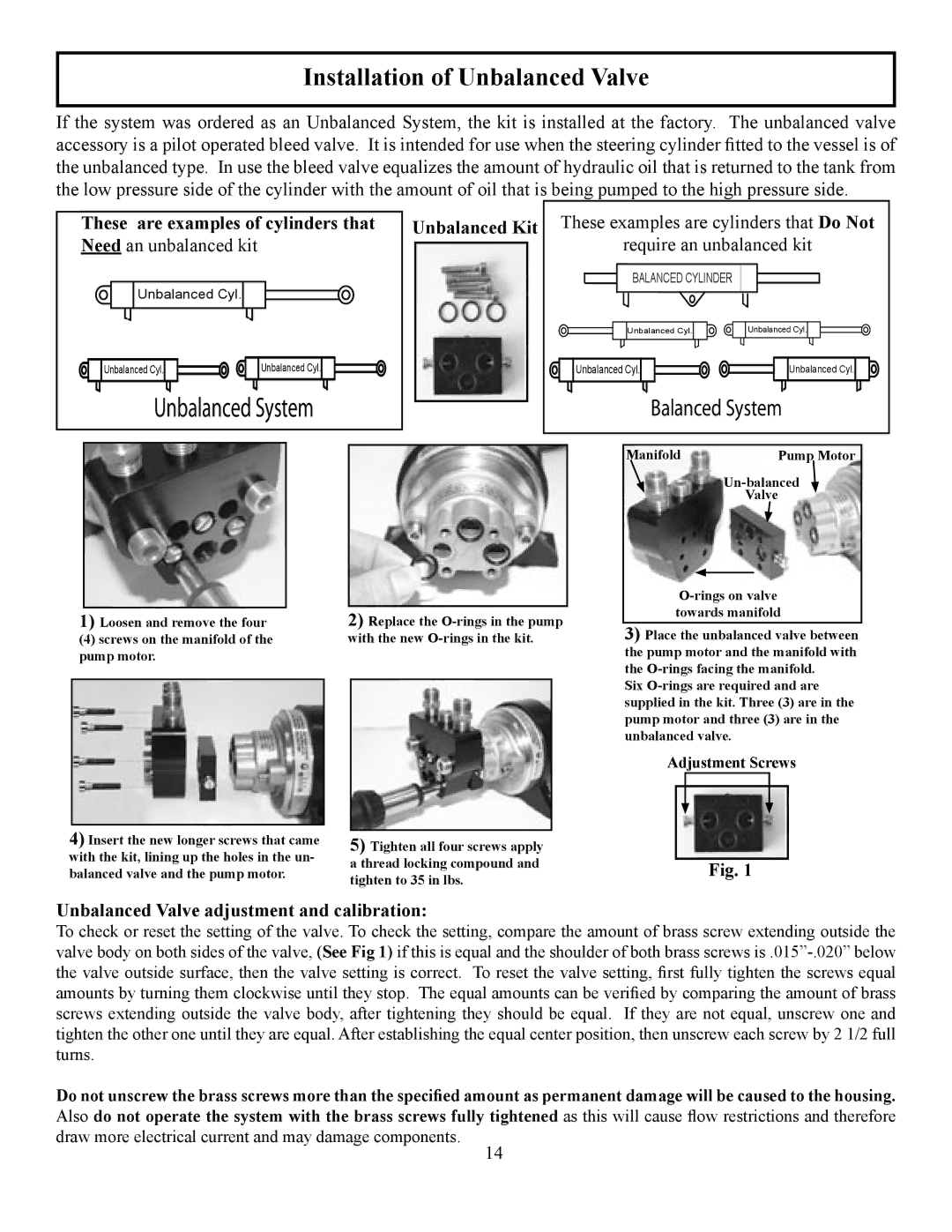
These are examples of cylinders that | Unbalanced Kit | These examples are cylinders that Do Not | ||
Need an unbalanced kit |
|
| require an unbalanced kit | |
Unbalanced Cyl. |
|
| BALANCED CYLINDER | |
|
|
|
| |
|
|
| Unbalanced Cyl. | Unbalanced Cyl. |
Unbalanced Cyl. | Unbalanced Cyl. |
| Unbalanced Cyl. | Unbalanced Cyl. |
���������� ������ |
| �������� ������ | ||
|
|
| Manifold | Pump Motor |
|
|
|
| |
|
|
|
| Valve |
|
|
|
|
|
|
|
|
|
| ||||
|
|
|
|
|
|
|
|
|
| towards manifold | |||
| 1) Loosen and remove the four | 2) Replace the | |||||||||||
|
| 3) Place the unbalanced valve between | |||||||||||
| (4) screws on the manifold of the | with the new |
| ||||||||||
| pump motor. |
|
|
|
|
| the pump motor and the manifold with | ||||||
|
|
|
|
|
|
|
|
| the | ||||
|
|
|
|
|
|
|
|
| Six | ||||
|
|
|
|
|
|
|
| ||||||
|
|
|
|
|
|
|
|
| supplied in the kit. Three (3) are in the | ||||
|
|
|
|
|
|
|
|
| pump motor and three (3) are in the | ||||
|
|
|
|
|
|
|
|
| unbalanced valve. | ||||
|
|
|
|
|
|
|
|
| Adjustment Screws | ||||
|
|
|
|
|
|
|
|
|
|
|
|
|
|
|
|
|
|
|
|
|
|
|
|
|
|
|
|
|
|
|
|
|
|
|
|
|
|
|
|
|
|
4) Insert the new longer screws that came |
|
|
|
|
|
|
|
|
|
| |||
|
| 5) Tighten all four screws apply |
|
|
|
|
|
| |||||
with the kit, lining up the holes in the un- |
|
| a thread locking compound and |
|
|
|
|
|
| ||||
|
|
|
|
| Fig. 1 | ||||||||
balanced valve and the pump motor. |
|
|
|
|
| ||||||||
|
| tighten to 35 in lbs. |
|
|
| ||||||||
|
|
|
|
|
|
|
|
|
|
|
| ||
Unbalanced Valve adjustment and calibration:
To check or reset the setting of the valve. To check the setting, compare the amount of brass screw extending outside the valve body on both sides of the valve, (See Fig 1) if this is equal and the shoulder of both brass screws
Do not unscrew the brass screws more than the specified amount as permanent damage will be caused to the housing. Also do not operate the system with the brass screws fully tightened as this will cause flow restrictions and therefore draw more electrical current and may damage components.
14