Hydraulic Layout for SeaStar Power Assisted Helms
SeaStar Power Assist
Hydraulic Layout
������������������������������������������
������������������������������������������������
��������������������������������������
R | P |
P= Port
R= Return
S= Starboard
��������������������������������������������������������������
�������������������������������������������������������������������
������������������������������������������������������������
�����������������������������������������������������
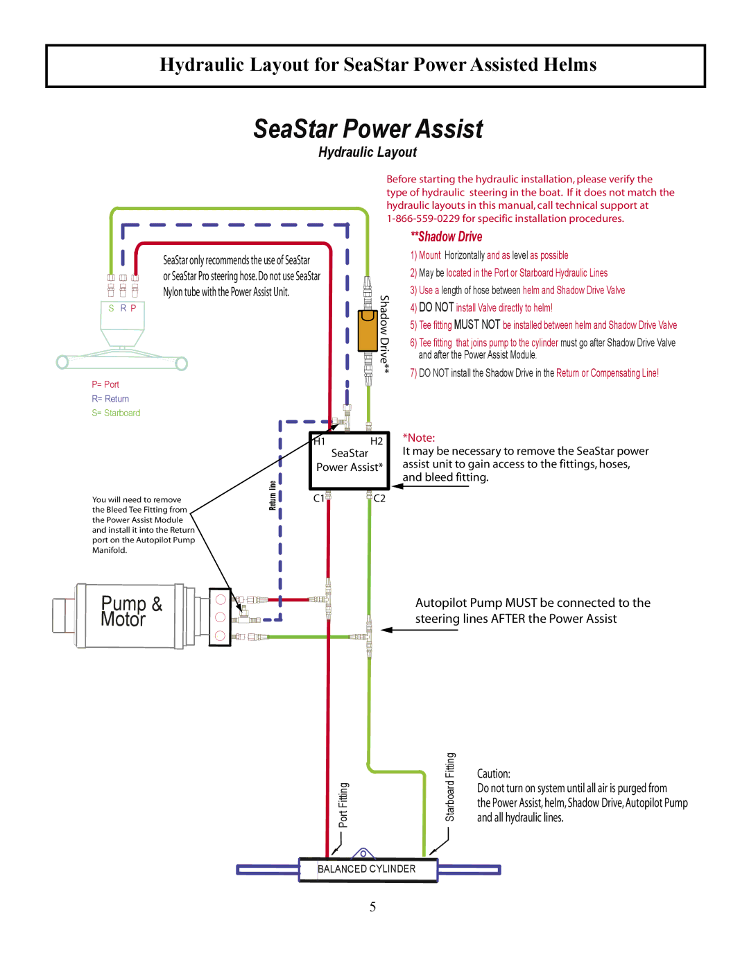
**Shadow Drive
1)Mount Horizontally and as level as possible
2)May be located in the Port or Starboard Hydraulic Lines
�������������� | 3) | Use a length of hose between helm and Shadow Drive Valve | |
4) | DO NOT install Valve directly to helm! | ||
| |||
| 5) | Tee fitting MUST NOT be installed between helm and Shadow Drive Valve | |
| 6) | Tee fitting that joins pump to the cylinder must go after Shadow Drive Valve | |
|
| and after the Power Assist Module. | |
| 7) | DO NOT install the Shadow Drive in the Return or Compensating Line! |
| line |
����������������������� | Return |
| |
�������������������������� |
|
����������������������� |
|
������������������������������ |
|
�������������������������� |
|
��������� |
|
Pump &
Motor
�� | �� | ������ | |
������� |
| ����������������������������������������������� | |
������������� | ��������������������������������������������������� | ||
������������������ | |||
|
| ||
�� | �� |
| |
����������������������������������������
�������������������������������������
FittingPort |
| Fitting |
|
| �������� | ||
|
| ||
| Starboard | �������������������������������������������������� | |
|
|
| |
|
|
| ���������������������������������������������������� |
|
|
| ������������������������� |
BALANCED![]() CYLINDER
CYLINDER
5
