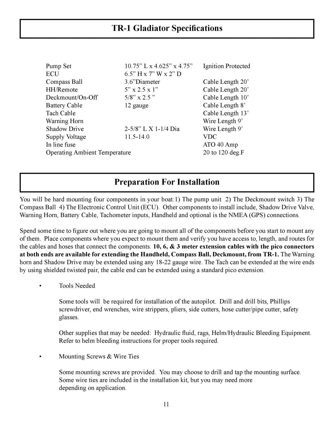
TR-1 Gladiator Specifications
Pump Set | 10.75” L x 4.625” x 4.75” | Ignition Protected |
ECU | 6.5” H x 7” W x 2” D |
|
Compass Ball | 3.6”Diameter | Cable Length 20’ |
HH/Remote | 5” x 2.5 x 1” | Cable Length 20’ |
5/8” x 2.5 ” | Cable Length 10’ | |
Battery Cable | 12 gauge | Cable Length 8’ |
Tach Cable |
| Cable Length 13’ |
Warning Horn |
| Wire Length 9’ |
Shadow Drive | Wire Length 9’ | |
Supply Voltage | VDC | |
In line fuse |
| ATO 40 Amp |
Operating Ambient Temperature | 20 to 120 deg.F | |
Preparation For Installation
You will be hard mounting four components in your boat:1) The pump unit 2) The Deckmount switch 3) The Compass Ball 4) The Electronic Control Unit (ECU). Other components to install include, Shadow Drive Valve, Warning Horn, Battery Cable, Tachometer inputs, Handheld and optional is the NMEA (GPS) connections.
Spend some time to figure out where you are going to mount all of the components before you start to mount any of them. Place components where you expect to mount them and verify you have access to, length, and routes for the cables and hoses that connect the components. 10, 6, & 3 meter extension cables with the pico connectors at both ends are available for extending the Handheld, Compass Ball, Deckmount, from
•Tools Needed
Some tools will be required for installation of the autopilot. Drill and drill bits, Phillips screwdriver, end wrenches, wire strippers, pliers, side cutters, hose cutter/pipe cutter, safety glasses.
Other supplies that may be needed: Hydraulic fluid, rags, Helm/Hydraulic Bleeding Equipment. Refer to helm bleeding instructions for proper tools required.
•Mounting Screws & Wire Ties
Some mounting screws are provided. You may choose to drill and tap the mounting surface. Some wire ties are included in the installation kit, but you may need more
depending on application.
11
