4K8 Switches
Trademarks
Magnum 4K-Series 4K8 Switches Installation and User Guide
Email support@garrettcom.com
Contacting GarrettCom, Inc
Introduction
Table of Contents
Troubleshooting
Personal Hubs, 10Mb series
Personal Switches , 10/100Mb
Media Converters, 10Mb and 100Mb series
Technical Specifications
DC Power Supply Options
Power Supply Internal
Warranty
LEDs Per Port
Ordering Information
Introduction Inspecting the Package and Product
Magnum 4K8 Switch chassis
Product Description Magnum 4K8 Switches
Front View
Rear View
3 Fiber-Port Modules, FPM-ST, FPM-SC, FPM-MTRJ
Fiber-port modules, 100Mb fiber
Fiber-port modules, 10 Mb fiber
5 10/100 Dual-speed Switched ports, RJ-45 copper
Frame Buffering and Latency
Magnum 4K8 Switches Installation and User Guide 10/04
„ Eight RJ-45 copper ports, 10/100 auto-negotiation
Features and Benefits
„ Full-duplex or Half-duplex operation, auto-sensing
Applications
Magnum 4K-Series Ethernet 10/100 Switch
Router 4b Magnum 4K8 provides a 100Mb backbone Switch
Locating Magnum 4K8 Switches
Installation
Connecting Fiber Optic ST-type, twist-lock
Connecting Ethernet Media
Ieee Standard Media Type Max. Distance Port Module Fiber
Copper
Connecting Single-Mode Fiber Optic
Connecting Fiber Optic SC-type, Snap-In
Media Ieee Standard
Rack-mounting
Are similar to the 19 brackets But use metric dimensions
Etsi European Telephone Standard brackets
Optional Brackets and the Etsi brackets
Preparation for Installing and Removing FPMs
Fiber Port Module FPM Installation
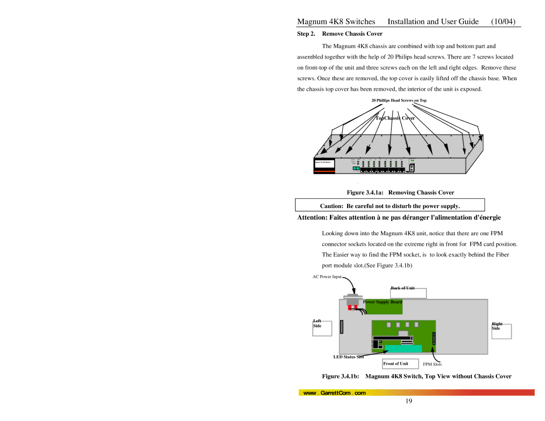
1a Removing Chassis Cover
Remove Chassis Cover
Before insertion
Installing FPM Cards in the Magnum 4K8 Switches
2b Inserting PM Cards into a Magnum 4K8
Removing FPM Cards from Magnum 4K8 Switches
3b Removing a FPM Card
Powering the Magnum 4K8 Switch
Filtering and Forwarding
Switching Functionality
Address Learning
Error
Manual Switches F-H, for FPM Port#9 only
Status LEDs
Auto-negotiation, for Fast Ethernet copper ports
Magnum 4K8 Switches Installation and User Guide 10/04
Flow-control, Ieee 802.3x standard
Auto-negotiation for 10/100Mb ports
Fiber Port Module
Inspecting the Package and Product Optional
Introduction Magnum 4K8 Fiber-Port Modules FPM
Product Description
FPM-MSC 100Mbps multi-mode FX-SC-type, snap-in connector
FPM-MST, 100Mbps multi-mode FX-ST-type, twist-lock connector
Activity 2 Link
FPM-SSC 100Mbps single-mode FX-SC-type, snap-in connector
100BASE-FX MT-RJ
Activity Link
FPM-Blank
FPM-Blank
Before Calling for Assistance
Return Material Authorization RMA Procedure
When Calling for Assistance
Shipping and Packaging Information
No Problem Found
B3.0 Applications for DC Powered Switches
Power Supply Internal 125 VDC Option Industrial Application
Figure B4.1 -48VDC Terminal Block on Magnum Ks-48VDC
B4.0 Installation
B4.1 UL Requirements
B7.0 Troubleshooting
B5.0 Operation
B6.0 Ordering Information
C5.0 Installation
C4.0 Features and Benefits of the DUAL-SOURCE Design
C3.0 DUAL-SOURCE OPTION, Theory of Operation
C6.0 Ordering Information
C5.1 UL Requirements
Example Magnum 4K8-48VDC
C7.0 Operation