INSTALLATION – WALL MOUNT
6.Connect the other end of the short telephone line cord to the wall phone jack.
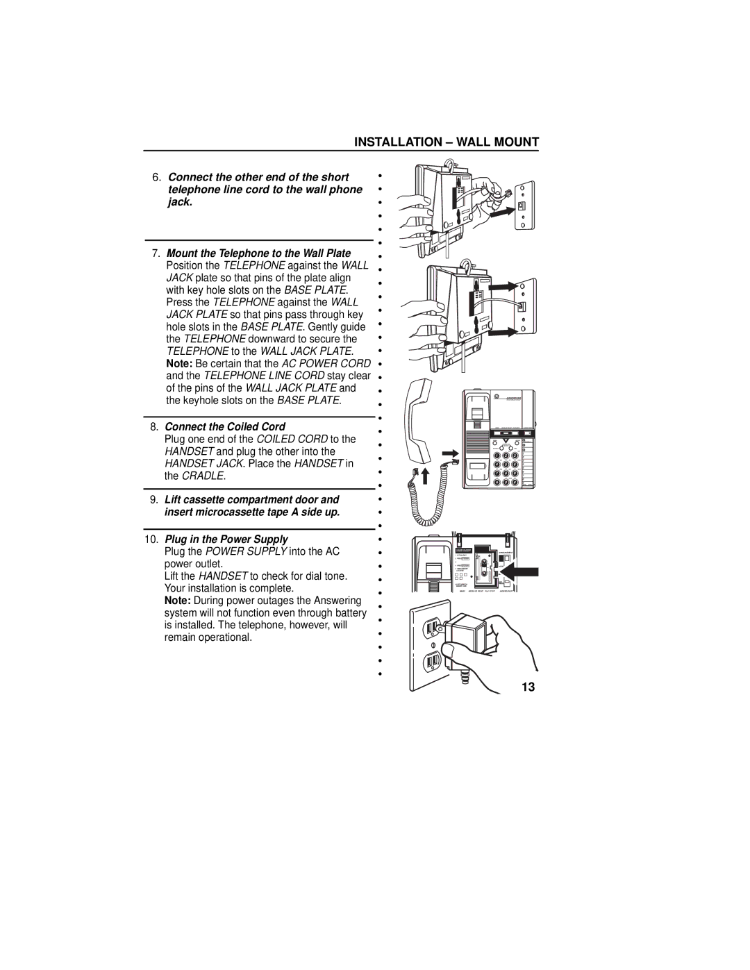
7.Mount the Telephone to the Wall Plate Position the TELEPHONE against the WALL JACK plate so that pins of the plate align with key hole slots on the BASE PLATE. Press the TELEPHONE against the WALL JACK PLATE so that pins pass through key hole slots in the BASE PLATE. Gently guide the TELEPHONE downward to secure the TELEPHONE to the WALL JACK PLATE. Note: Be certain that the AC POWER CORD and the TELEPHONE LINE CORD stay clear of the pins of the WALL JACK PLATE and the keyhole slots on the BASE PLATE.
8.Connect the Coiled Cord
Plug one end of the COILED CORD to the HANDSET and plug the other into the HANDSET JACK. Place the HANDSET in the CRADLE.
9.Lift cassette compartment door and insert microcassette tape A side up.
10.Plug in the Power Supply
Plug the POWER SUPPLY into the AC power outlet.
Lift the HANDSET to check for dial tone. Your installation is complete.
Note: During power outages the Answering system will not function even through battery is installed. The telephone, however, will remain operational.
•
•
•
•
•
•
•
•
•
•
•
•
•
•
•
•
•
•
•
•
•
•
•
•
•
•
•
•
•
•
•
•
•
•
•
•
•
•
|
| ANSWERPHONE |
| |
1 | 2 | 3 | 1 | |
2 | ||||
|
|
| 3 | |
4 | 5 | 6 | 4 | |
|
|
| 5 | |
7 | 8 | 9 | 6 | |
7 | ||||
|
|
| ||
| 0 | # | 8 | |
| 9 |
| TO STORE TELEPHONE |
|
| NUMBERS IN MEMORY | ANNOUNCEMENT |
|
| |
1. | LIFT HANDSET |
|
2. | PRESS STORE/IN |
|
3. |
|
|
4. PRESS STORE/IN | HOUR | |
5. | PRESS MEMORY |
|
| LOCATION |
|
|
| MINUTE |
|
| DAY |
6.WRITE NAME ON | TIMECHECK | |
| MEMORY CARD |
|
MEMO MESSAGE RESET PLAY•STOP | ANSWER ON/OFF |
13