Préparation pour l’installation – Vidange

PRÉPARATION DE LA PLOMBERIE POUR LA VIDANGE

Exigences relatives au système de vidange

Veuillez observer les ordonnances et les codes locaux en vigueur.

Le boyau de vidange doit avoir une longueur maximale de 3 mètres (10 pieds).

Il faut prévoir une boucle de vidange élevée

ou l’installation d’une coupure anti-refoulement. Voir ci-dessous.

Méthode de vidange

Le type d’installation de vidange dépend des conditions suivantes :

Les ordonnances ou codes locaux en vigueur exigent-ils une coupure anti-refoulement?

Le raccord en T se trouve-t-il à moins de 46 cm

(18 po) du plancher?

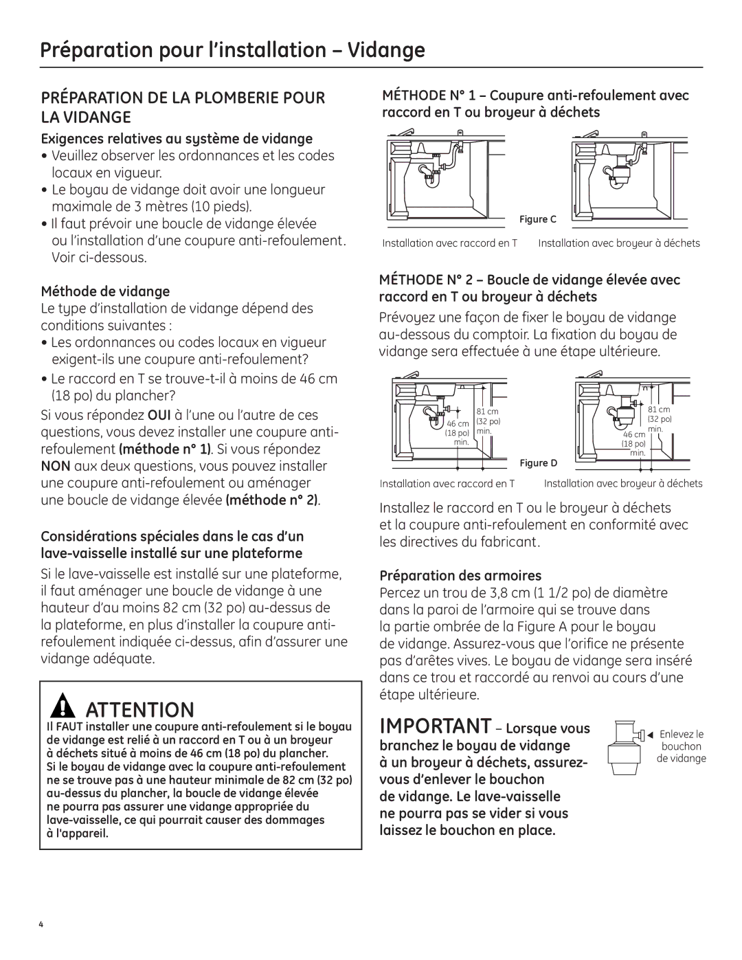
Si vous répondez OUI à l’une ou l’autre de ces questions, vous devez installer une coupure anti- refoulement (méthode n° 1). Si vous répondez NON aux deux questions, vous pouvez installer une coupure anti-refoulement ou aménager une boucle de vidange élevée (méthode n° 2).

Considérations spéciales dans le cas d’un lave-vaisselle installé sur une plateforme

Si le lave-vaisselle est installé sur une plateforme, il faut aménager une boucle de vidange à une hauteur d’au moins 82 cm (32 po) au-dessus de la plateforme, en plus d’installer la coupure anti- refoulement indiquée ci-dessus, afin d’assurer une vidange adéquate.

ATTENTION

Il FAUT installer une coupure anti-refoulement si le boyau de vidange est relié à un raccord en T ou à un broyeur

à déchets situé à moins de 46 cm (18 po) du plancher.

Si le boyau de vidange avec la coupure anti-refoulement ne se trouve pas à une hauteur minimale de 82 cm (32 po) au-dessus du plancher, la boucle de vidange élevée

ne pourra pas assurer une vidange appropriée du lave-vaisselle, ce qui pourrait causer des dommages à l'appareil.

MÉTHODE N° 1 – Coupure anti-refoulement avec raccord en T ou broyeur à déchets

Figure C

Installation avec raccord en T Installation avec broyeur à déchets

MÉTHODE N° 2 – Boucle de vidange élevée avec raccord en T ou broyeur à déchets

Prévoyez une façon de fixer le boyau de vidange au-dessous du comptoir. La fixation du boyau de vidange sera effectuée à une étape ultérieure.


81 cm

81 cm


32"

46 cm

32"

(32 po)

(32 po)

Min.

18"

Min.

18"min.

(18 po)

min.

Min.


46 cm

min.


Min.


(18 po)


min.

Figure D

Installation avec raccord en T

Installation avec broyeur à déchets

Installez le raccord en T ou le broyeur à déchets et la coupure anti-refoulement en conformité avec les directives du fabricant.

Préparation des armoires

Percez un trou de 3,8 cm (1 1/2 po) de diamètre dans la paroi de l’armoire qui se trouve dans la partie ombrée de la Figure A pour le boyau

de vidange. Assurez-vous que l’orifice ne présente pas d’arêtes vives. Le boyau de vidange sera inséré dans ce trou et raccordé au renvoi au cours d’une étape ultérieure.

IMPORTANT Lorsque vous


EnlRemovevezl


branchez le boyau de vidange


bouchon


Drain


Plug

à un broyeur à déchets, assurez-


de vidange


vous d’enlever le bouchon de vidange. Le lave-vaisselle ne pourra pas se vider si vous laissez le bouchon en place.

4

Page 20
Image 20
GE 206C1559P195 Préparation pour l’installation Vidange, Préparation DE LA Plomberie Pour LA Vidange

206C1559P195 specifications

The GE 206C1559P195 is a component that belongs to General Electric's suite of high-performance aircraft engine components. Specifically, this part is integral to the Geared Turbofan (GTF) engine technology that GE has pioneered, aiming at increasing fuel efficiency while reducing noise and emissions.

One of the standout features of the GE 206C1559P195 is its advanced aerodynamic design, which plays a crucial role in optimizing the engine's performance. The component helps improve air flow, thereby enhancing thrust and operational efficiency. By utilizing sophisticated Computational Fluid Dynamics (CFD) simulations in its design process, GE has ensured that the part meets the rigorous demands of modern aviation.

The GE 206C1559P195 also incorporates cutting-edge materials technology. Constructed with lightweight yet robust materials, the part significantly contributes to the overall weight reduction of the engine, which is vital for maximizing fuel efficiency. The use of composite materials and advanced alloys ensures that the component can withstand extreme temperatures and pressures associated with high-performance engine operation.

Another characteristic that sets the GE 206C1559P195 apart is its reliability and durability. GE's stringent manufacturing processes and quality control protocols ensure that each component is built to last, reducing maintenance frequency and enhancing operational reliability. The part is designed to have a long service life, making it a cost-effective choice in the long run for airlines and operators.

In terms of technological innovation, the GE 206C1559P195 features integrated sensors that provide real-time data on engine performance. This capability allows for better monitoring and predictive maintenance, thereby increasing safety and reducing unscheduled downtimes.

Furthermore, the integration of digital twin technology enables operators to simulate different operational scenarios, improving decision-making and optimizing maintenance schedules. This technological edge places the GE 206C1559P195 at the forefront of aircraft engine component innovations, aligning with the industry's shift toward sustainability and efficiency.

In summary, the GE 206C1559P195 is a remarkable component that embodies GE's commitment to advance aviation technology, emphasizing performance, durability, and environmental awareness. Its design and technological features reflect the ongoing evolution in the aerospace industry, making it a key asset for modern aircraft engines.