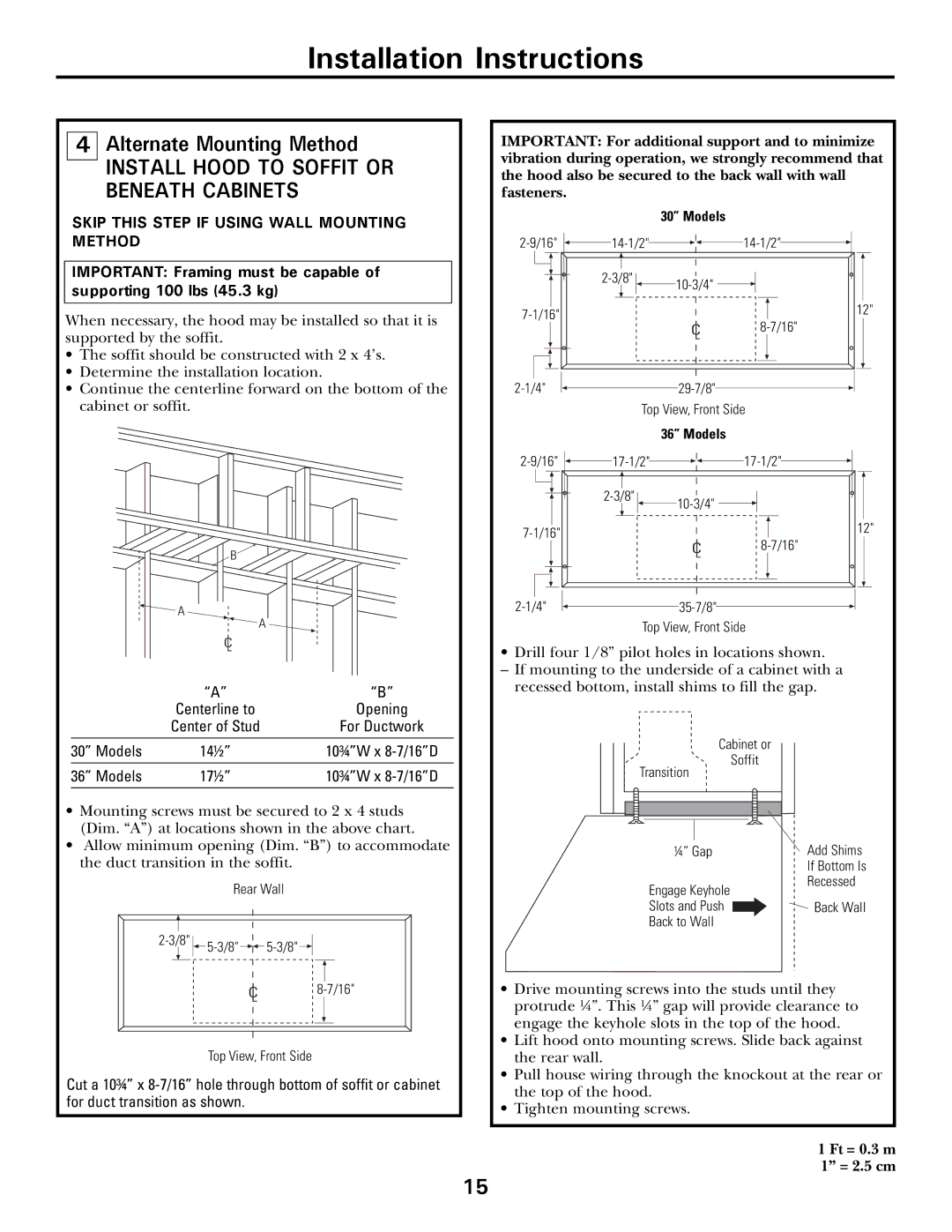
CV936 specifications
The GE CV936 is a versatile and powerful gas turbine designed for use in a variety of industrial and power generation applications. With its advanced design and state-of-the-art technologies, the CV936 represents a significant step forward in the field of aeroderivative gas turbines.One of the standout features of the GE CV936 is its impressive efficiency. This turbine achieves a fuel efficiency rate that allows operators to maximize output while minimizing fuel consumption, thereby reducing overall operating costs. The efficiency extends beyond fuel usage, contributing to lower emissions as the turbine is designed to comply with rigorous environmental regulations.
The CV936 incorporates advanced aerodynamics in its design. Its blades are engineered using sophisticated computer modeling techniques that enhance airflow and optimize performance. The materials chosen for these components are lightweight yet durable, which contributes to the turbine’s ability to operate at high temperatures without degradation in performance.
A significant technology aspect of the GE CV936 is its modular design. This feature not only simplifies maintenance but also allows for quick and efficient upgrades as technology evolves. Operators can benefit from improved performance without needing to replace the entire turbine, which can be a cost-effective solution for many businesses.
Another characteristic that sets the CV936 apart is its robust control system. Coupled with advanced sensors and data analytics capabilities, the turbine provides real-time monitoring and operational insights. This allows for proactive maintenance strategies, reducing downtime and extending the operational lifespan of the equipment.
The turbine's design also accommodates a wide variety of fuels, making it exceptionally flexible for different operational contexts. Whether used in simple cycle, combined cycle, or cogeneration setups, the CV936 can efficiently use natural gas and liquid fuels, giving operators the flexibility to adapt to their specific energy needs.
In summary, the GE CV936 gas turbine is a cutting-edge solution that combines high efficiency, advanced aerodynamics, modular design, and robust control technologies. Its ability to adapt to various fuel types and configurations makes it an excellent choice for companies looking to optimize their power generation capabilities while minimizing environmental impact.

