Sequence of Operation
Standard Transition
Source 1 Power Failure:
When Source 1 voltage or frequency has fallen below the preset "Fail" values, the controller initiates the Time Delay Source 2 Start Timer (Engine Start Timer "P") cycle. Upon completion of the (P) time delay, an Engine start Signal is sent to Source 2. When Source 2 voltage and frequency reach the preset "Restore" Values, the time delay to Source 2 Timer (W) begins its timing cycle to ensure voltage and frequency stabilization before transfer. A manual pushbutton BYPASS is provid- ed to bypass the "W" time delay if desired. After the (W) time delay, the CCE relay energizes the CE solenoid to close the transfer switch in to Source 2. The SE limit switch activates to
Restoration of Source 1 Power:
When Source 1 power reach the preset "Restore" values, the controller initiates
Immediately after
Delayed Transition
Source 1 Power Failure:
When Source 1 voltage or frequency has fallen below the preset "Fail" values, the controller initiates the Time Delay Source 2 Start (Engine Start Timer "P") cycle. Upon completion of the (P) time delay, an Engine start Signal is sent to Source 2. When Source 2 voltage and frequency reach the preset "Restore" values, the time delay to open Source 1 timer (W) begins its timing cycle to ensure voltage and frequency stabiliza- tion before
Restoration of Source 1 Power:
When Source 1 power reach the preset "Restore" values, the controller initiates
Immediately after
|
|
|
|
|
|
|
|
|
|
|
|
|
|
| Table 3 |
|
|
|
|
|
|
|
|
|
|
|
|
|
|
| |
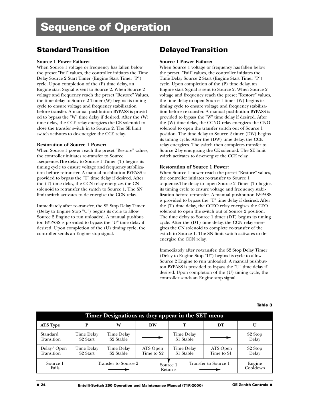
| Timer Designations as they appear in the SET menu |
| |||||||||||||
|
|
|
|
|
|
|
|
|
|
|
|
|
|
|
|
ATS Type | P |
| W |
| DW |
| T |
|
| DT | U | ||||
|
|
|
|
|
|
|
|
|
|
|
|
|
|
| |
Standard | Time Delay | Time Delay |
|
|
| Time Delay |
|
|
|
| S2 Stop | ||||
Transition | S2 Start |
| S2 Stable |
|
|
| S1 Stable |
|
|
|
| Delay | |||
|
|
|
|
|
|
| |||||||||
|
|
|
|
|
|
|
|
|
|
|
|
|
|
| |
Delay/ Open | Time Delay | Time Delay |
| ATS Open | Time Delay |
| ATS Open | S2 Stop | |||||||
Transition | S2 Start |
| S2 Stable |
| Time to S2 | S1 Stable |
| Time to S1 | Delay | ||||||
|
|
|
|
|
|
|
|
|
|
|
|
|
|
|
|
Source 1 | Transfer to Source 2 |
| Source 1 | Transfer to Source 1 | Engine | ||||||||||
Fails |
|
|
|
|
|
|
|
|
|
|
|
| Cooldown | ||
|
|
|
|
|
| Returns |
|
|
|
|
|
| |||
|
|
|
|
|
|
|
|
|
|
|
|
|
| ||
|
|
|
|
|
|
|
|
|
|
|
|
|
|
|
|
■ 24 | GE Zenith Controls ■ |