Installation (cont’d)
Initial Energization (cont’d)
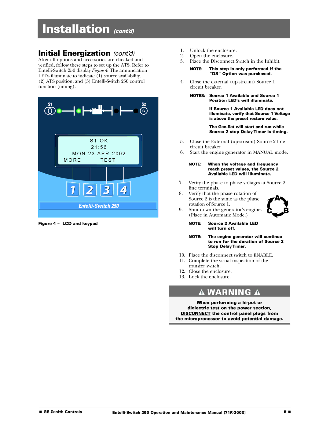
After all options and accessories are checked and verified, follow these steps to set up the ATS. Refer to
(2)ATS position, and (3)
S 1 O K
2 1 : 5 6
M O N 2 3 A P R 2 0 0 2
M O R E T E S T
Figure 4 – LCD and keypad
1.Unlock the enclosure.
2.Open the enclosure.
3.Place the Disconnect Switch in the Inhibit.
NOTE: This step is only performed if the “DS” Option was purchased.
4.Close the external
NOTES: Source 1 Available and Source 1 Position LED’s will illuminate.
If Source 1 Available LED does not illuminate, verify that Source 1 Voltage is above the preset restore value.
The
Source 2 stop Delay Timer is timing.
5.Close the External
6.Start the engine generator in MANUAL mode.
NOTE: When the voltage and frequency reach preset values, the Source 2 Available LED will illuminate.
7.Verify the phase to phase voltages at Source 2 line terminals.
8.Verify that the phase rotation of
Source 2 is the same as the phase rotation of Source 1.
9.Shut down the generator's engine.
(Place in Automatic Mode.)
NOTE: Source 2 Available LED will turn off.
NOTE: The engine generator will continue to run for the duration of Source 2 Stop Delay Timer.
10.Place the disconnect switch to ENABLE.
11.Complete the visual inspection of the transfer switch.
12.Close the enclosure.
13.Lock the enclosure.
![]() WARNING
WARNING ![]()
When performing a
dielectric test on the power section,
DISCONNECT the control panel plugs from
the microprocessor to avoid potential damage.
■ GE Zenith Controls | 5 ■ |