2 |
Configuration
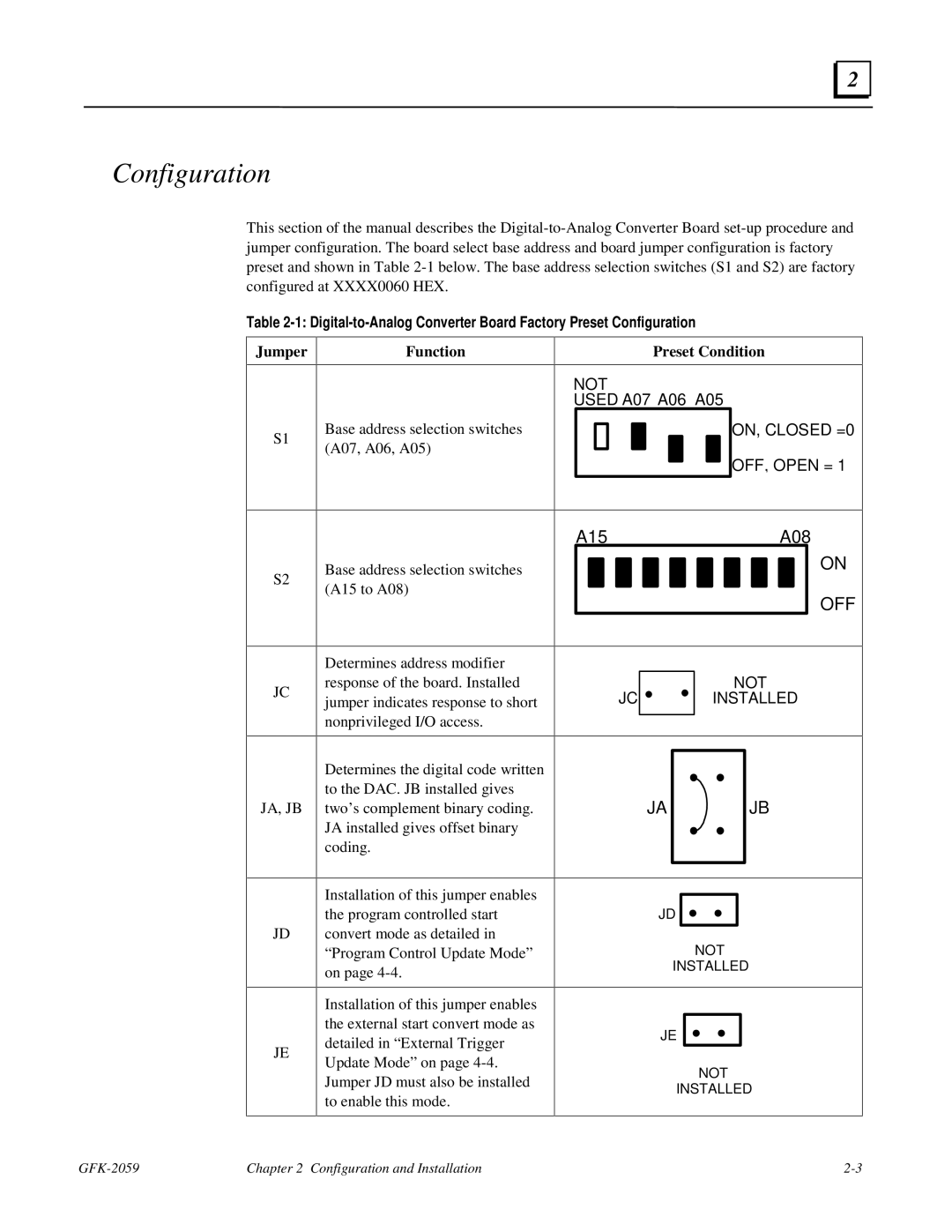
This section of the manual describes the
Table
Jumper | Function |
|
|
Preset Condition
NOT
USED A07 A06 A05
S1
Base address selection switches (A07, A06, A05)
ON, CLOSED =0
OFF, OPEN = 1
S2
JC
JA, JB
Base address selection switches (A15 to A08)
Determines address modifier response of the board. Installed jumper indicates response to short nonprivileged I/O access.
Determines the digital code written to the DAC. JB installed gives two’s complement binary coding. JA installed gives offset binary coding.
A15A08
ON
OFF
| NOT |
JC | INSTALLED |
JA | JB |
JD
JE
Installation of this jumper enables the program controlled start convert mode as detailed in “Program Control Update Mode” on page
Installation of this jumper enables the external start convert mode as detailed in “External Trigger Update Mode” on page
JD
NOT
INSTALLED
JE
NOT
INSTALLED
Chapter 2 Configuration and Installation |