3 |
Digital-to-Analog Converter Board Programming Options
There are two types of registers that must be written to for proper operation of the DAC board. One is the CSR, and the other is the DAC. The order in which they are written to may differ depending on the method used to start a conversion.
Immediate DAC Update Mode
The IMMEDIATE DAC UPDATE MODE is described in “Program Control Update Mode” on page
All eight DAC channels can be initiated to a value, as described in the preceding paragraph, before they are connected to the external circuitry. After powering up the board, load the DAC channels with the initial
Table
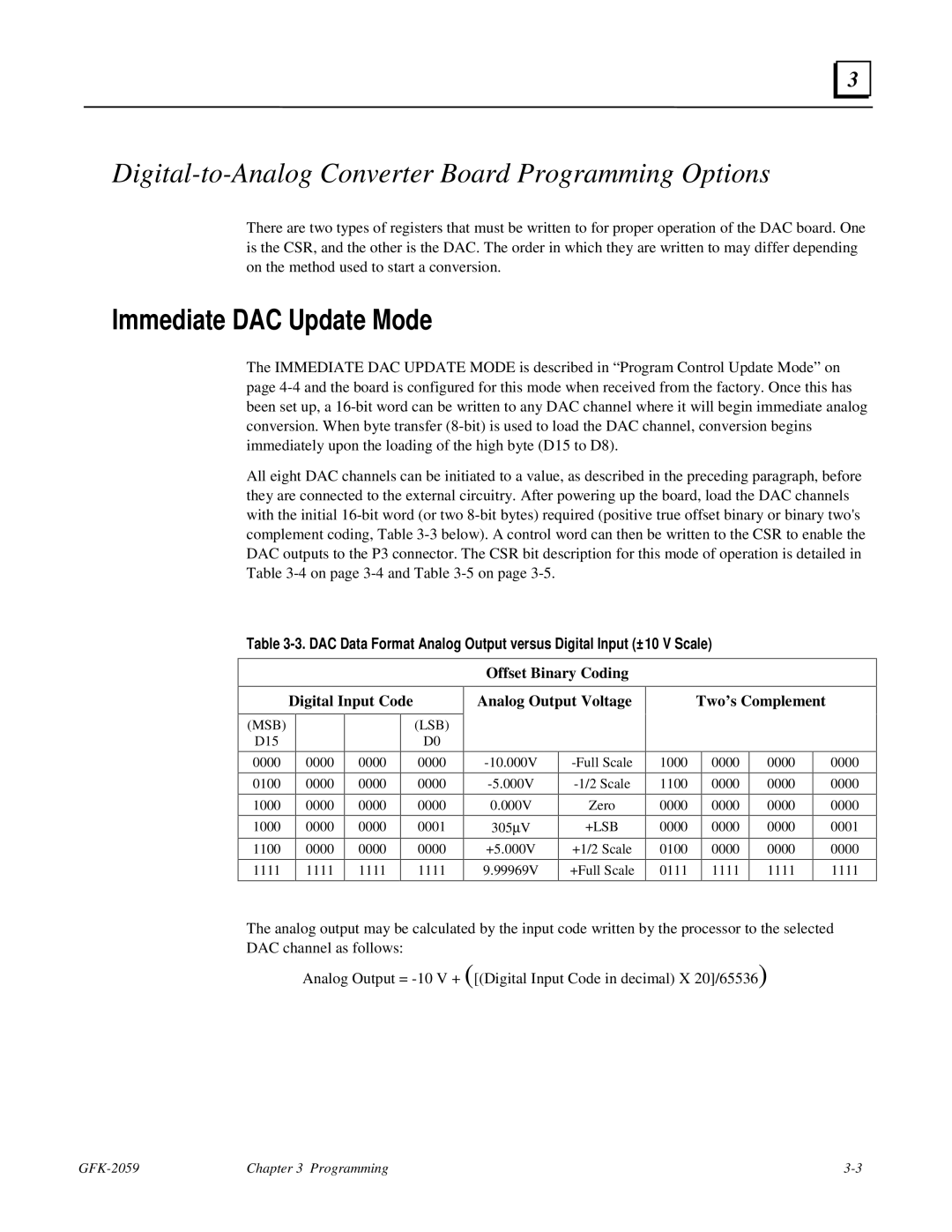
Digital Input Code
Offset Binary Coding
Analog Output Voltage | Two’s Complement |
|
|
(MSB)
D15
0000
0100
1000
1000
1100
1111
0000
0000
0000
0000
0000
1111
0000
0000
0000
0000
0000
1111
(LSB)
D0
0000
0000
0000
0001
0000
1111
0.000V
305μV
+5.000V
9.99969V
Zero
+LSB
+1/2 Scale
+Full Scale
1000
1100
0000
0000
0100
0111
0000
0000
0000
0000
0000
1111
0000
0000
0000
0000
0000
1111
0000
0000
0000
0001
0000
1111
The analog output may be calculated by the input code written by the processor to the selected
DAC channel as follows:
Analog Output =
Chapter 3 Programming |