Board Address Selection Switches
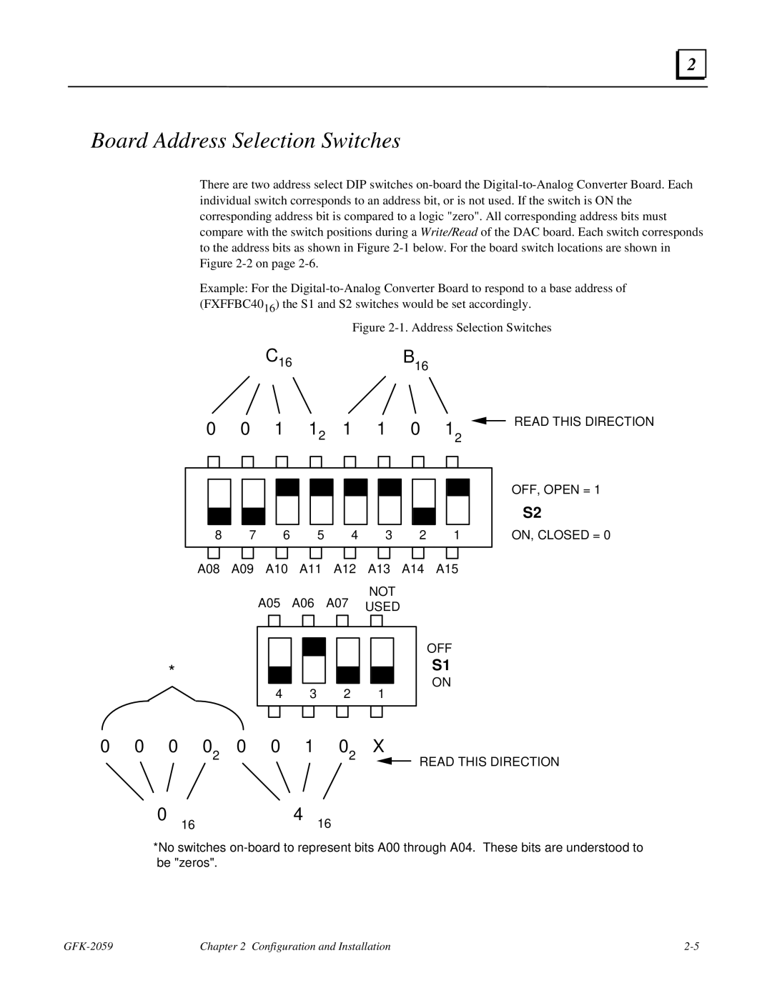
There are two address select DIP switches on-board the Digital-to-Analog Converter Board. Each individual switch corresponds to an address bit, or is not used. If the switch is ON the corresponding address bit is compared to a logic "zero". All corresponding address bits must compare with the switch positions during a Write/Read of the DAC board. Each switch corresponds to the address bits as shown in Figure 2-1 below. For the board switch locations are shown in Figure 2-2 on page 2-6.
Example: For the Digital-to-Analog Converter Board to respond to a base address of (FXFFBC4016) the S1 and S2 switches would be set accordingly.
Figure 2-1. Address Selection Switches
C16B16
A08 A09 A10 A11 A12 A13 A14 A15
NOT
A05 A06 A07 USED
READ THIS DIRECTION
OFF, OPEN = 1
S2
ON, CLOSED = 0
| | | | | | | | | | | | | | |
0 | 0 | 0 | 02 | 0 | 0 | 1 | 02 | X |
| | 0 | 16 | | | 4 | 16 | | | | | | READ THIS DIRECTION |
| | | | | | | | | |
*No switches on-board to represent bits A00 through A04. These bits are understood to be "zeros".
GFK-2059 | Chapter 2 Configuration and Installation | 2-5 |

