Plan the Wiring
1.The downdraft blower system draws 4 AMPS and requires a 120 VAC, 60 Hz circuit.
2.The unit has a 2 ft. long power cord with a
Preparation
Changing Blower Discharge (Optional)
The blower is shipped with its discharge facing DOWN. Follow these steps ONLY if:
•The position of the blower discharge needs to be moved so the ductwork does not interfere with the floor joists, plumbing or wiring below.
•It is necessary to rotate the blower discharge to the RIGHT or LEFT.
Place the unit on its back on a table or work surface.
DOWN DISCHARGE–
Moving Blower Left or Right
Sheet metal screw
Blower
Nuts
|
|
|
| |
|
|
|
| |
|
| Bottom | ||
Clamp channel | ||||
flange | ||||
|
| |||
1.Loosen the 4 nuts and 2 clamp channels.
2.Slide the blower to the desired position.
3.Use the supplied cover plate to close the open space (if any).
4.Tighten the nuts to secure the top of the blower and use the sheet metal screws through the bottom flange to secure the bottom of the blower.
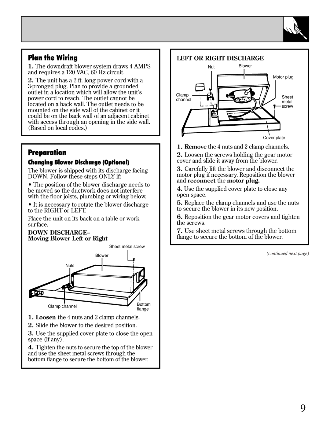
LEFT OR RIGHT DISCHARGE
|
|
| Nut |
| Blower |
|
|
|
|
|
| |||
|
|
|
|
|
|
|
|
|
|
|
|
|
|
|
|
|
|
|
|
|
|
|
|
|
|
|
|
|
|
|
|
|
|
|
|
|
|
|
| Motor plug | ||||
|
|
|
|
|
|
|
|
|
|
|
|
|
|
|
|
|
|
|
|
|
|
|
|
|
|
|
|
|
|
|
|
|
|
|
|
|
|
|
|
|
|
|
|
|
Clamp |
|
|
|
|
|
|
|
|
| |||||
|
|
|
|
|
|
|
|
|
|
|
| Sheet | ||
channel |
|
|
|
|
|
|
|
|
|
|
| |||
|
|
|
|
|
|
|
|
|
|
| metal | |||
|
|
|
|
|
|
|
|
|
|
|
|
| ||
|
|
|
|
|
|
|
|
|
|
|
|
| screw | |
|
|
|
|
|
|
|
|
|
|
|
|
| ||
|
|
|
|
|
|
|
|
|
|
|
|
|
|
|
Cover plate
1.Remove the 4 nuts and 2 clamp channels.
2.Loosen the screws holding the gear motor cover and slide it away from the blower.
3.Carefully lift the blower and disconnect the motor plug if necessary. Reposition the blower and reconnect the motor plug.
4.Use the supplied cover plate to close any open space.
5.Replace the clamp channels and use the nuts to secure the blower in its new position.
6.Reposition the gear motor covers and tighten the screws.
7.Use sheet metal screws through the bottom flange to secure the bottom of the blower.
(continued next page)
9