Making Cable Connections |
5MAKING CABLE CONNECTIONS
Note: This camera is 24 VAC only.
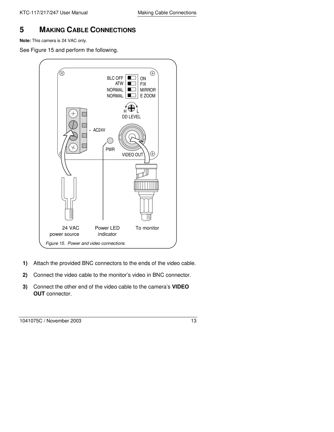
See Figure 15 and perform the following.
24 VAC | Power LED | To monitor |
power source | indicator |
|
Figure 15. Power and video connections
1)Attach the provided BNC connectors to the ends of the video cable.
2)Connect the video cable to the monitor’s video in BNC connector.
3)Connect the other end of the video cable to the camera’s VIDEO OUT connector.
1041075C / November 2003 | 13 |
