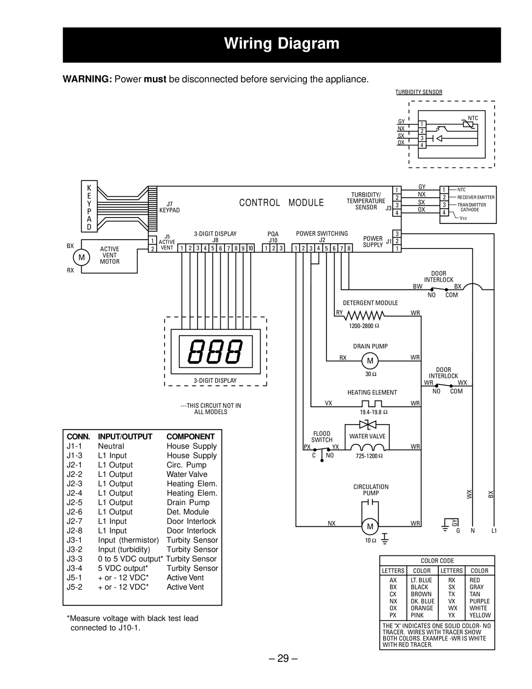
Wiring Diagram

WARNING: Power must be disconnected before servicing the appliance.

TURBIDITY SENSOR

K

E

Y

P

A

D

BXACTIVE

MVENT

MOTOR

RX


CONTROL

MODULE


TURBIDITY/


J7


TEMPERATURE


KEYPAD


SENSOR

J3


J5

3-DIGIT DISPLAY


PQA

POWER SWITCHING

POWER


1


J8


J10


J2


J1

ACTIVE


3


4


5


6


7 8

9


10

1


2


3

1


2


3


4


5


6


7


8

SUPPLY


2

VENT 1 2


GY

NTC

1

NX

2

SX

3

OX

4


1

GY

1

NTC


NX


2


2

RECEIVER EMITTER


SX


3

3

TRANSMITTER


OX


4

CATHODE

4


Vcc


3

2

1

DOOR

INTERLOCK

BWBX


NO

COM


DETERGENT MODULE


RY


WR


1200-2800


DRAIN PUMP


RX

M

WR


30

DOOR

3-DIGIT DISPLAY


INTERLOCK


WR

WX


HEATING ELEMENT

NO

COM

---THIS CIRCUIT NOT IN

VX


WR


ALL MODELS


19.4-19.8


CONN.

INPUT/OUTPUT

COMPONENT

J1-1

Neutral

House Supply

J1-3

L1 Input

House Supply

J2-1

L1 Output

Circ. Pump

J2-2

L1 Output

Water Valve

J2-3

L1 Output

Heating Elem.

J2

-4

L1 Output

Heating Elem.


J2

-5

L1 Output

Drain Pump

J2

-6

L1 Output

Det. Module

J2

-7

L1 Input

Door Interlock

J2

-8

L1 Input

Door Interlock

J3

-1

Input (thermistor)

Turbity Sensor

J3

-2

Input (turbidity)

Turbity Sensor

J3

-3

0 to 5 VDC output* Turbity Sensor

J3

-4

5 VDC output*

Turbity Sensor

J5

-1

+ or - 12 VDC*

Active Vent

J5

-2

+ or - 12 VDC*

Active Vent

*Measure voltage with black test lead connected to J10-1.

FLOOD

WATER VALVE

SWITCH


PX

YX

WR

C

NO

725-1200


CIRCULATION


WX

BX


PUMP


NX


WR

GY


M


G

N

L1


10


COLOR CODE


LETTERS

COLOR

LETTERS

COLOR


AX

LT. BLUE

RX

RED


BX

BLACK

SX

GRAY


CX

BROWN

TX

TAN


NX

DK. BLUE

VX

PURPLE


OX

ORANGE

WX

WHITE


PX

PINK

YX

YELLOW

THE "X" INDICATES ONE SOLID COLOR- NO

TRACER. WIRES WITH TRACER SHOW

BOTH COLORS. EXAMPLE -WR IS WHITE

WITH RED TRACER.

– 29 –

Page 31
Image 31
GE EDW4060, PDW7300, PDW7700, GSD6600, GSD6700, GSD6660, GSD6200, GSD6300, PDW7880, PDW7800, EDW4000 Wiring Diagram, Control Module

EDW4000, EDW4060, PDW7800, PDW7880, GSD6300 specifications

The GE GLD4000, GHDA600, GLD6000, GLD5000, and EDW4000 models are part of GE's innovative portfolio of industrial and commercial power generation solutions. Each model boasts a unique set of features and technologies designed to meet specific operational needs and efficiency standards in the power generation sector.

Starting with the GE GLD4000, this model is renowned for its high reliability and versatility in various applications. Equipped with advanced digital controls, the GLD4000 integrates seamlessly into existing infrastructure. It features exceptional fuel efficiency and can operate efficiently across different fuel types, including natural gas and diesel. The compact design allows for simplified installation and maintenance, making it a preferred choice for businesses aiming to reduce downtime and operating costs.

Moving on to the GHDA600, this model emphasizes robustness and durability, designed for rugged environments. The GHDA600 is particularly suited for remote locations where traditional power sources may be unavailable. With its integrated thermal management system, it can operate reliably even in extreme temperatures. The unit’s modular design allows for scalability, enabling customers to expand power capabilities as their needs grow.

The GE GLD6000 stands out in the lineup for its high performance and energy output. This model includes advanced monitoring systems that provide real-time data analytics, enhancing operational efficiency. The GLD6000 is engineered for low emissions and adheres to stringent environmental standards. Its advanced cooling and lubrication technologies ensure optimal performance while minimizing wear and tear.

In contrast, the GLD5000 emphasizes flexibility and customization. This model can be tailored to meet specific operational requirements, making it suitable for a wide range of applications, from industrial plants to commercial buildings. Enhanced connectivity features allow for remote monitoring and management, giving operators greater control over performance metrics and energy consumption.

Lastly, the EDW4000 is designed for emergency and backup power applications. It features quick start capabilities and robust energy storage options to ensure power delivery during outages. The unit’s design prioritizes safety and reliability, with advanced fire suppression and environmental protection measures. Its compact footprint makes it ideal for urban settings where space is at a premium.

Together, these GE models represent a comprehensive approach to energy solutions, combining innovative technology, efficiency, and adaptability to meet diverse power generation needs across various industries.