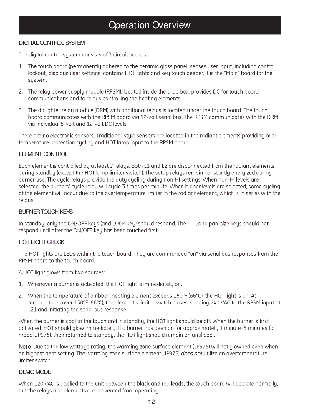
PP975, PP945 specifications
The GE PP945 and PP975 are two advanced gas ranges that showcase General Electric's commitment to innovation, performance, and user convenience. These models have become popular choices among home chefs looking for reliable appliances that optimize cooking experiences.The GE PP945 features an induction cooktop with four cooking elements that provide precise temperature control and rapid heat adjustment. Induction technology is notable for its ability to heat cookware directly, leading to faster cooking and additional energy efficiency. With its sleek design, this model not only enhances kitchen aesthetics but also enables easy cleaning thanks to its flat surface. The oven in the PP945 provides true European convection, which utilizes a fan and additional heating element to circulate hot air evenly throughout the oven cavity. This results in improved baking performance and more consistent results across multiple racks.
On the other hand, the GE PP975 takes cooking convenience a step further with its range of smart features, including Wi-Fi connectivity that allows users to control their oven remotely via a smartphone app. This capability enables home cooks to preheat the oven or adjust cooking settings from virtually anywhere, adding unparalleled convenience to meal preparation. The PP975 also features a self-cleaning option, utilizing high-temperature cleaning to reduce food residue to ash, making maintenance simple and hassle-free.
Both models are equipped with a variety of cooking modes, including bake, broil, and various convection options, catering to diverse culinary techniques. The advanced oven design includes steam-cleaning options, which offer homeowners an environmentally friendly and efficient way to tackle spills and splatters without harsh chemicals.
Additional features include oven racks that are easily adjustable, precise temperature probes for meat, and large capacity ovens that can accommodate multiple dishes simultaneously. Safety features such as automatic shut-off and a child lock ensure that cooking remains safe for families.
In summary, the GE PP945 and PP975 are designed for those seeking a blend of modern technology and traditional cooking styles. With standout features such as induction cooking, smart technology, and efficient cleaning options, both ranges are well-equipped to enhance the cooking experience and meet the demands of today’s culinary enthusiasts. Whether you choose the PP945 for its induction efficiency or the PP975 for its smart capabilities, both models represent the forefront of cooking innovation.
