Section 2 — Post Installation Start-up and Adjustments
◆ 2.7.1 ADDITIONAL CORROSION PROTECTION
Do not make any unnecessary adjustments.
!Factory settings are correct for most applica- tions. However, when making adjustments, be careful to avoid overspeeding the engine.
If this procedure or equipment are not available to you, locate the Generac Dealer nearest you and they can perform the adjustments.
NOTE:
A service fee may be charged for this adjustment.
2.7ENGINE GOVERNOR ADJUSTMENT
If both AC frequency and voltage are correspondingly high or low, adjust the engine governor as follows:
1.Loosen governor clamp bolt.
2.Completely remove the idle spring.
3.With governor arm at wide open throttle position, rotate governor shaft fully clockwise. Tighten clamp bolt to 84
4.Start unit and apply full load. Use full load speed adjust screw (Figure 2.4) to adjust frequency to 58 Hz.
5.Remove load, stop engine, loosen the idle adjust screw and reconnect the idle spring.
6.Using your hand, push the governor arm to the closed throttle position. Make sure the idle spring does not stretch at all.
7.Restart the unit.
8.Slowly turn the idle adjust screw to adjust the no- load idle frequency to
9.The governor is now set.
Figure 2.4 — Full Load Speed Adjust Screw
Full Load Speed Adjust Screw
Periodically spray all engine linkage parts and brack- ets with corrosion inhibiting spray such as
2.8VOLTAGE REGULATOR
ADJUSTMENT
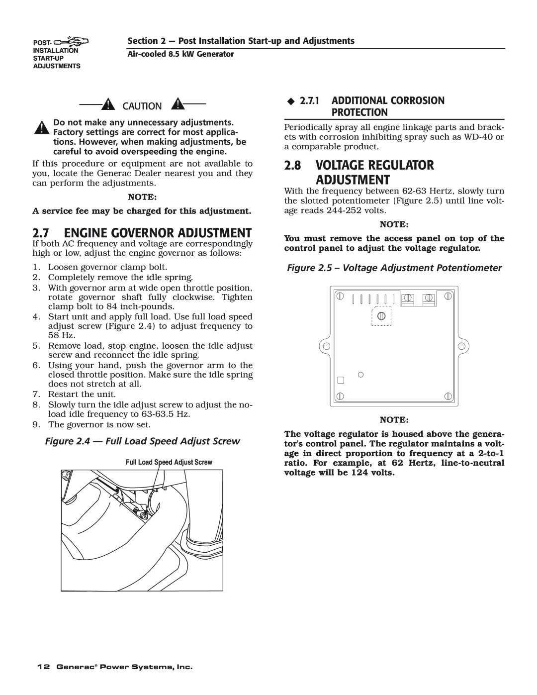
With the frequency between
NOTE:
You must remove the access panel on top of the control panel to adjust the voltage regulator.
Figure 2.5 – Voltage Adjustment Potentiometer
NOTE:
The voltage regulator is housed above the genera- tor's control panel. The regulator maintains a volt- age in direct proportion to frequency at a
12 Generac® Power Systems, Inc.
