Installation and Owner’s Manual
POWER SYSTEMS, INC
DEADLY EXHAUST FUMES OUTDOOR INSTALLATION ONLY
DANGER
CONTENTS
OPERATION AND MAINTENANCE
HOW TO OBTAIN SERVICE
INTRODUCTION
Introduction
GENERAL HAZARDS
DANGER
SAVE THESE INSTRUCTIONS
– The manufacturer
ELECTRICAL HAZARDS
FIRE HAZARDS
EXPLOSION HAZARDS
STANDARDS INDEX
1.3 SYSTEM SET LED
1.1UNPACKING/INSPECTION
1.2PROTECTION SYSTEMS
Exhaust Enclosure Fuel Regulator 12 Volt Battery
1.4YOUR GENERATOR
Data
Decal
1.5SPECIFICATIONS
1.5.1 GENERATOR
1.5.2 ENGINE
Section 1 - General Information
1.8RECONFIGURING THE FUEL SYSTEM
1.6FUEL REQUIREMENTS AND RECOMMENDATIONS
1.7FUEL CONSUMPTION
Figure 1.2 – Demand Regulator
1.10 BATTERY INSTALLATION
1.11 THE BATTERY
1.9.2 TRANSFER SWITCH
Figure 1.5 – Battery Cable Connections
2.2CHECK TRANSFER SWITCH OPERATION
2.1BEFORE INITIAL START-UP
2.3ELECTRICAL CHECKS
•Wear rubber gloves and boots
2.4GENERATOR TESTS UNDER LOAD
DANGER
DANGER
DANGER
2.6ADJUSTING THE REGULATOR NATURAL GAS ONLY
Figure 2.2 — Placement of Regulator
2.5CHECKING AUTOMATIC OPERATION
Figure 2.1 — Dual Fuel Regulators
2.7ENGINE GOVERNOR ADJUSTMENT
2.8VOLTAGE REGULATOR ADJUSTMENT
Figure 2.4 — Full Load Speed Adjust Screw
Figure 2.5 – Voltage Adjustment Potentiometer
3.1 BREAK-INPROCEDURE
3.3AUTOMATIC TRANSFER OPERATION
3.2.3 “MANUAL” POSITION
3.2.1 “AUTO” POSITION
Figure 3.2 – Manual Transfer Switch Operation
3.5.1 TRANSFER TO GENERATOR POWER SOURCE
3.4SEQUENCE OF AUTOMATIC OPERATION
3.5MANUAL TRANSFER OPERATION
3.6SETTING THE EXERCISE TIMER
3.5.2 TRANSFER BACK TO UTILITY POWER SOURCE
3.7.1 LOW OIL PRESSURE SWITCH
3.7.2 HIGH TEMPERATURE SWITCH
4.2CHECKING THE ENGINE OIL LEVEL
4.1FUSE
3.7.3.1 Approximate Crank Cycle Times
3.7.4 OVERSPEED
4.5CHANGING THE ENGINE AIR CLEANER
4.3.2 OIL CHANGE PROCEDURE
4.3CHANGING THE ENGINE OIL
4.4CHANGING THE OIL FILTER
4.7BATTERY MAINTENANCE
Figure 4.4 — 12 kW and 15 kW Engine Air Cleaner
Figure 4.5 – Setting the Spark Plug Gap
4.6SPARK PLUGS
4.8 ADJUSTING VALVE CLEARANCE
Figure 4.6 - Valve Clearance Adjustment
4.9COOLING SYSTEM
Figure 4.7 – Cooling Vent Locations
4.11 OUT OF SERVICE PROCEDURE
4.11.2 RETURN TO SERVICE
4.11.1 REMOVAL FROM SERVICE
4.10 ATTENTION AFTER SUBMERSION
4.13 SERVICE SCHEDULE
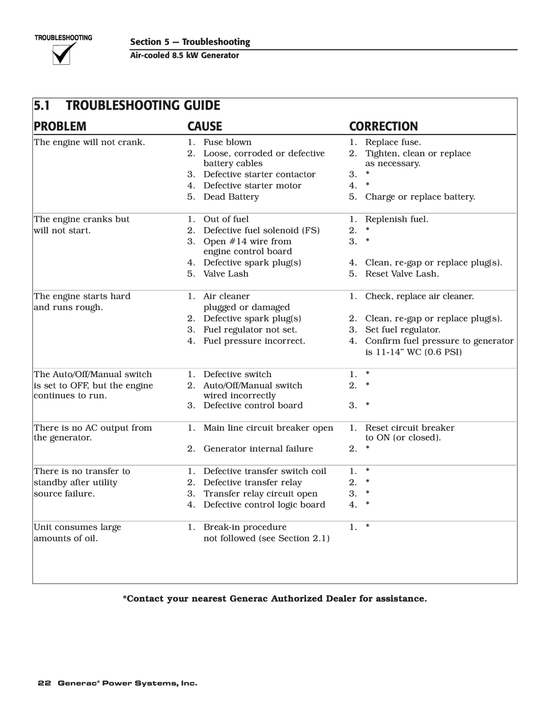
5.1TROUBLESHOOTING GUIDE
PROBLEM
CAUSE
CORRECTION
6 - Mounting Dimensions
Generac Power Systems, Inc
Air-cooled8.5 kW Generator Drawing No. 0D3739-A
REAR VIEW
Wiring Diagram - Drawing No. 0D8500
24 Generac Power Systems, Inc
Section 7 — Electrical Data
Air-cooled8.5 kW Generator
Generac Power Systems, Inc.
Section 7 — Electrical Data
CUSTOMER
CONNECTION
Electrical Schematic - Drawing No. 0D8501
26 Generac Power Systems, Inc
Section 7 — Electrical Data
Air-cooled8.5 kW Generator
Generac Power Systems, Inc.
Section 7 — Electrical Data
Section 8 — Exploded Views and Parts Lists
28 Generac Power Systems, Inc
Air-cooled8.5 kW Generator
Compartment - Drawing No. 0D8445-A
Section 8 — Exploded Views and Parts Lists
PART NO
DESCRIPTION
PART NO
30 Generac Power Systems, Inc
Air-cooled8.5 kW Generator
Engine & Alternator – Drawing No. 0D8446
Section 8 — Exploded Views and Parts Lists
ITEM
PART NO
DESCRIPTION
Section 8 — Exploded Views and Parts Lists
Air-cooled8.5 kW Generator
Engine – Drawing No. 0D8674-CPart
Section 8 - Exploded Views and Parts Lists
PART NO
DESCRIPTION
DESCRIPTION
Section 8 — Exploded Views and Parts Lists
34 Generac Power Systems, Inc
Section 8 — Exploded Views and Parts Lists
PART NO
DESCRIPTION
DESCRIPTION
Section 8 — Exploded Views and Parts Lists
Control Panel Assembly – Drawing No. 0D8503-B
36 Generac Power Systems, Inc
Air-cooled8.5 kW Generator
Section 8 — Exploded Views and Parts Lists
PART NO
DESCRIPTION
DESCRIPTION
Section 8 - Exploded Views and Parts Lists
PART NO
DESCRIPTION
PART NO
Section 8 — Exploded Views and Parts Lists
FOR GT
ENGINE ONLY
DESCRIPTION
YOUR WARRANTY RIGHTS AND OBLIGATIONS
PURCHASER’S/OWNER’S WARRANTY RESPONSIBILITIES
1-800-333-1322
CALIFORNIA EMISSION CONTROL WARRANTY STATEMENT
EMISSION CONTROL SYSTEM WARRANTY
EMISSION RELATED PARTS INCLUDE THE FOLLOWING
Section 9 – Warranty
WARRANTY SCHEDULE
Section 9 – Warranty
GENERAC POWER SYSTEMS, INC
P.O. BOX WHITEWATER, WI