Contents
Authorized Dealer Support
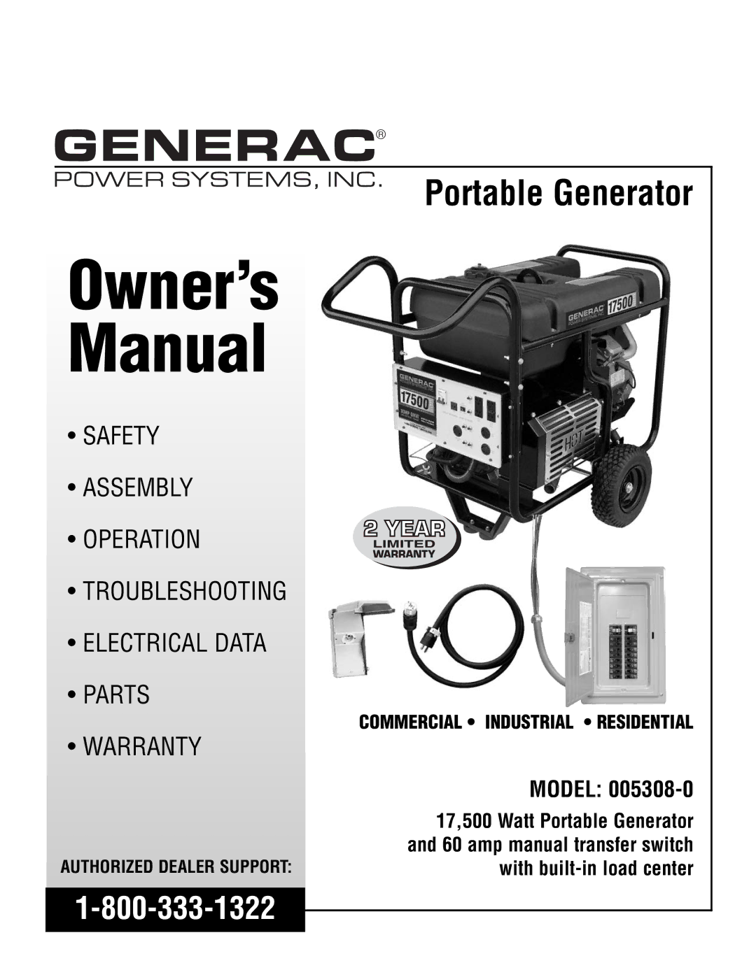
Owner’s Manual
Troubleshooting
Table of Contents Residential Portable Generator System
Read this Manual Thoroughly
Never operate in an enclosed area or indoors
General Hazards
Explosion Hazards
Electrical Hazards
Fire Hazards
Unpacking
Accessory BOX
Assembling the Wheel KIT
Assembling the Handle
Handle Assembly
Battery Connection
Operation Residential Portable Generator System
Know the Generator
This generator
Volt AC, 20A Duplex Gfci Receptacle
1 AC, 20 AMP, Duplex Receptacle
Cord Sets and Connection Plugs
2 120V AC, 20 AMP, Gfci Receptacle
Provided. This receptacle can not recharge 6 Volt batteries
5 12 Volt DC, 10 AMP Receptacle
Connecting Electrical Loads
HOW to USE the Generator
DON’T Overload the Generator
Grounding the Generator
Before Starting the Generator
Wattage Reference Guide
Adding Engine OIL
Adding Gasoline
To Start the Engine
LOW OIL Pressure Shutdown System
Automatic Idle Control
Stopping the Engine
To recharge 12 Volt batteries, proceed as follows
Charging a Battery
Maintenance Residential Portable Generator System
Maintenance Schedule
Engine Maintenance Checking OIL Level
Generator Maintenance
To Clean the Generator
General Recommendations
Clean Spark Arrestor Screen
Service AIR Cleaner
Replacing the Spark Plug
To adjust valve clearance
Adjusting Valve Clearance
Long Term Storage
General
Other Storage Tips
Troubleshooting
KIT Includes
Installation for Manual Transfer Switch
Tools Required
Items YOU Must Purchase
Silicone Caulk
These Instructions are to Serve AS a Guide only
7a Prepare Box For Connections
Your Generac Manual Transfer Switch is now installed
Operation of Generator with Manual Transfer Switch
Using the Ultra Source Portable
Transfer to Generator Power Source When Utility Power Fails
Transfer Back to Utility Power Source
Interconnection Drawing
Residential Portable Generator System
Wiring Diagram, Portable Generator Drawing No G0731
Closest to Bearing
Schematic, Portable Generator Drawing No G0733
Wiring Diagram, Manual Transfer Switch Drawing No G1065
Manual Transfer Switch with Load Center Drawing No G0939-B
Description
Exploded Views and Parts Lists
System
160
QTY Description
Lists
118 116 119162
QTY Description Part NO#
Generator Drawing No D4488-F
QTY Description
Control Panel Drawing No G0727-B
Part NO. QTY Description
Tray
Rubber Tank Mount
MANUFACTURER’S Emission Control System Warranty Coverage
Emission Control System Warranty
Warranty Schedule