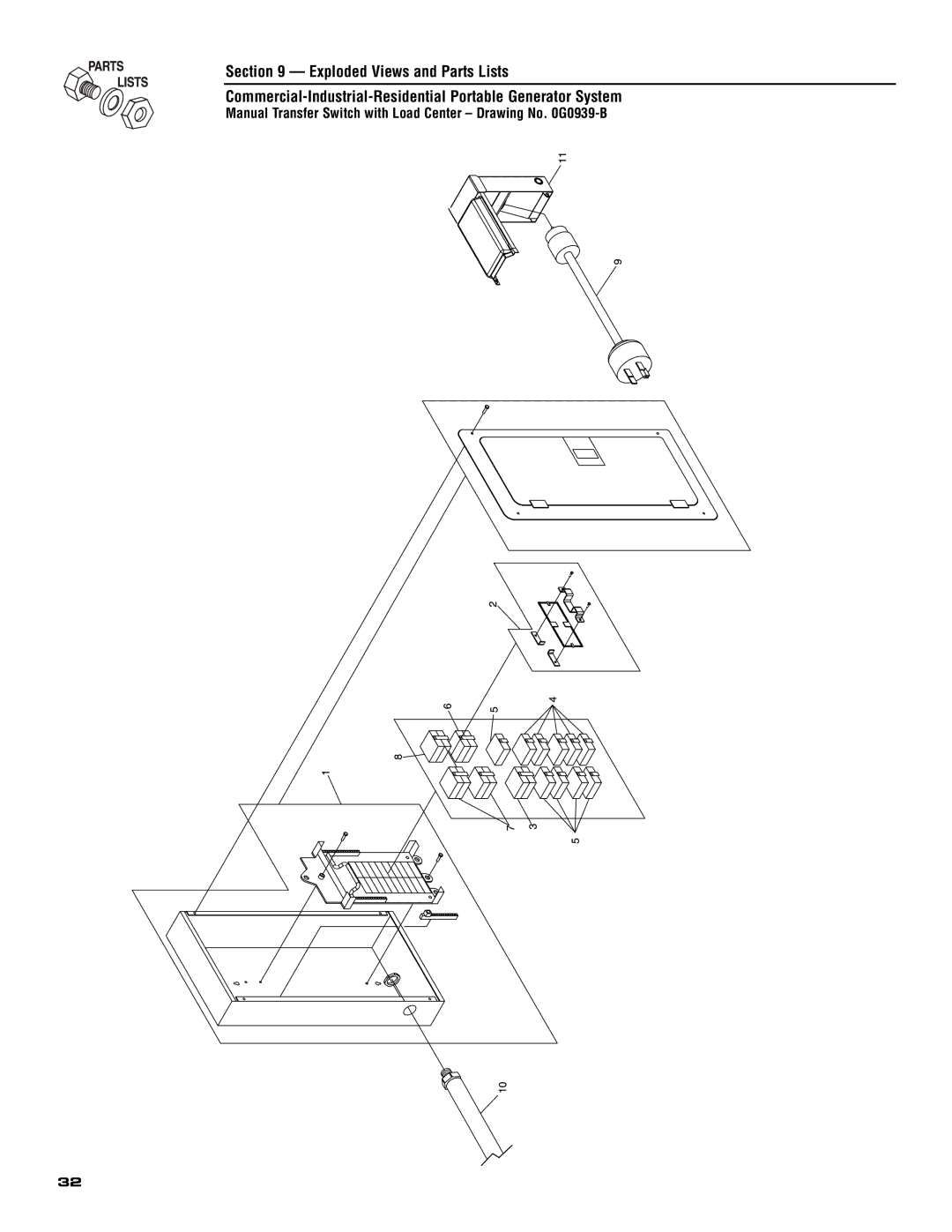
17,500 Watt Portable Generator
and 60 amp manual transfer switch
MODEL
with built-in load center
Section 5 - Installation Guide For
Safety Rules
Section 3 - Maintenance
Manual Transfer Switch
INTRODUCTION
DANGER
READ THIS MANUAL THOROUGHLY
This symbol points out potential explosion hazard
DANGER
GENERAL HAZARDS
IMPORTANT SAFETY INSTRUCTIONS Residential Portable Generator System
Never operate in an enclosed area or indoors
FIRE HAZARDS
ELECTRICAL HAZARDS
EXPLOSION HAZARDS
STANDARDS INDEX
Shipping Bracket
1.1.1 ACCESSORY BOX
1.1 UNPACKING
1.2.1 ASSEMBLING THE WHEEL KIT
Figure 3 - Battery Connections
1.2.3 BATTERY CONNECTION
Figure 2 - Handle Assembly
Section 1 - General Information Residential Portable Generator System
1512
OPERATION
2.1 KNOW THE GENERATOR
Figure 4 - Control Panel
2.2.2 120V AC, 20 AMP, GFCI RECEPTACLE
2.2 CORD SETS AND CONNECTION PLUGS
2.2.1 AC, 20 AMP, DUPLEX RECEPTACLE
2.2.3 120V AC, 30 AMP RECEPTACLE
2.2.6 120/240 VOLT AC, 50 AMP RECEPTACLE
2.2.5 12 VOLT DC, 10 AMP RECEPTACLE
2.2.4 120/240V AC, 30 AMP RECEPTACLE
50 A
2.4 DON’T OVERLOAD THE GENERATOR
2.3 HOW TO USE THE GENERATOR
2.3.2 CONNECTING ELECTRICAL LOADS
2.3.1 GROUNDING THE GENERATOR
2.6.1 ADDING ENGINE OIL
2.5 WATTAGE REFERENCE GUIDE
2.6 BEFORE STARTING THE GENERATOR
Section 2 - Operation Residential Portable Generator System
Figure 16 - Idle Control Switch
2.7 TO START THE ENGINE
2.6.2 ADDING GASOLINE
Figure 14 - Fuel Tank
2.8 STOPPING THE ENGINE
2.9 AUTOMATIC IDLE CONTROL
2.11 LOW OIL PRESSURE SHUTDOWN SYSTEM
2.11.1 INITIAL START-UP
Section 2 - Operation Residential Portable Generator System
2.12 CHARGING A BATTERY
To recharge 12 Volt batteries, proceed as follows
3.2.1 GENERATOR SPECIFICATIONS
3.1 MAINTENANCE SCHEDULE
PRODUCT SPECIFICATIONS
3.2.2 ENGINE SPECIFICATIONS
3.3.2 TO CLEAN THE GENERATOR
3.3.1 GENERATOR MAINTENANCE
3.3.3 ENGINE MAINTENANCE
3.3 GENERAL RECOMMENDATIONS
3.3.6 REPLACING THE SPARK PLUG
3.4 SERVICE AIR CLEANER
3.5 CLEAN SPARK ARRESTOR SCREEN
Figure 20 - Air Cleaner
Section 3 - Maintenance Residential Portable Generator System
3.6 ADJUSTING VALVE CLEARANCE
Figure 22 - Valve Clearance Adjustment
To adjust valve clearance
3.9 OTHER STORAGE TIPS
3.7 GENERAL
3.8 LONG TERM STORAGE
Section 3 - Maintenance Residential Portable Generator System
SOLUTION
4.1 TROUBLESHOOTING
SYMPTOM
CAUSE
KIT INCLUDES
1. Power Inlet Box
26 UL listed wire nuts not shown
TOOLS REQUIRED
1. PLAN THE LOCATION OF YOUR GENERATOR
THESE INSTRUCTIONS ARE TO SERVE AS A GUIDE ONLY
Section 5-Installation for Manual Transfer Switch
1-3/4” Diameter Hole
9 Mounting Manual Transfer Switch
Section 5-Installation for Manual Transfer Switch
Existing Wire
7a Prepare Box For Connections
Your GENERAC Manual Transfer Switch is now installed
Section 6-Operation of Generator with Manual Transfer Switch
USING THE ULTRA SOURCE PORTABLE
17,500 WATT PORTABLE COMPONENTS
Power Inlet Box with 50 Amp Male Receptacle 15 Foot Power Cord with
TRANSFER BACK TO UTILITY POWER SOURCE
TRANSFER TO GENERATOR POWER SOURCE WHEN UTILITY POWER FAILS
INTERCONNECTION DRAWING
Section 6-Operation of Generator with Manual Transfer Switch
Section 7 - Notes Residential Portable Generator System
Section 8 - Electrical Data
Wiring Diagram, Portable Generator - Drawing No. 0G0731
ENGINE WIRING
Commercial-Industrial-Residential Portable Generator System
Wiring Diagram, Portable Generator - Drawing No. 0G0731
Section 8 - Electrical Data
STATOR
Section 8 - Electrical Data
Schematic, Portable Generator - Drawing No. 0G0733
RESET TEST RESET TEST
Commercial-Industrial-Residential Portable Generator System
Wiring Diagram, Manual Transfer Switch - Drawing No. 0G1065
Section 8 - Electrical Data
GROUND GRN
Manual Transfer Switch with Load Center - Drawing No. 0G0939-B
Section 9 - Exploded Views and Parts Lists
Commercial-Industrial-Residential Portable Generator System
Section 9 - Exploded Views and Parts Lists
DESCRIPTION
System
Section 9 - Exploded Views and Parts Lists
14 22
59 3, 30, 35 60 2, 5, 17, 18, 34, 35, 40, 57, 139 61 8, 11, 12
GT-990 & GT-760 Engine Page 1 - Drawing No. 0E8589-N
Section 9 - Exploded Views and Parts Lists
Commercial-Industrial-Residential Portable Generator System
DESCRIPTION
System
DETAIL A
118
Lists
GT-990 & GT-760 Engine Page 2 - Drawing No. 0E8589-N
Section 9 - Exploded Views and Parts Lists
Commercial-Industrial-Residential Portable Generator System
PART #
Commercial-Industrial-Residential Portable Generator System
Section 9 - Exploded Views and Parts Lists
Generator - Drawing No. 0D4488-F
DESCRIPTION
Section 9 - Exploded Views and Parts Lists
Commercial-Industrial-Residential Portable Generator System
DESCRIPTION
Commercial-Industrial-Residential Portable Generator System
Section 9 - Exploded Views and Parts Lists
Control Panel - Drawing No. 0G0727-B
PART NO. QTY
Section 9 - Exploded Views and Parts Lists
Commercial-Industrial-Residential Portable Generator System
DESCRIPTION
Tray
Section 9 - Exploded Views and Parts Lists
POWER WIRE TO ENGINE
Detail
DESCRIPTION
Section 9 - Exploded Views and Parts Lists
Commercial-Industrial-Residential Portable Generator System
DESCRIPTION
MANUFACTURER’S EMISSION CONTROL SYSTEM WARRANTY COVERAGE
CALIFORNIA EMISSION CONTROL WARRANTY STATEMENT
YOUR WARRANTY RIGHTS AND OBLIGATIONS
PURCHASERS/OWNERS WARRANTY RESPONSIBILITIES
EMISSION RELATED PARTS INCLUDE THE FOLLOWING
EMISSION CONTROL SYSTEM WARRANTY
Section 10 - Warranty
Commercial-Industrial-Residential Portable Generator System
WARRANTY SCHEDULE
GENERAC POWER SYSTEMS “TWO YEAR” LIMITED WARRANTY FOR GENERAC
17,500 WATT PORTABLE GENERATOR WITH MANUAL TRANSFER SWITCH
CONSUMER APPLICATION