Section 2 – Operation
Residential Portable Generator System
2.3 HOW TO USE THE GENERATOR
If you have any problems operating your generator, please call the generator helpline at
2.3.1 GROUNDING THE GENERATOR
The National Electrical Code requires that the frame and external electrically conductive parts of this generator be properly connected to an approved earth ground. Local electrical codes may also require proper grounding of the unit. For that purpose, generally, connecting a No. 10 AWG (American Wire Gauge) stranded copper wire to the grounding wing nut and to an
2.3.2 CONNECTING ELECTRICAL LOADS
DO NOT connect 240 Volt loads to 120 Volt receptacles. DO NOT connect
•Let engine stabilize and warm up for a few minutes after starting.
•Plug in and turn on the desired 120 or 240 Volt AC, single phase, 60 Hz electrical loads.
•Add up the rated watts (or amps) of all loads to be connected at one time. This total should not be greater than (a) the rated wattage/amperage capacity of the generator or (b) circuit breaker rating of the receptacle supplying the power. See "Don't Overload the Generator" below.
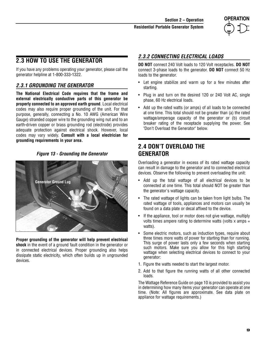
Figure 13 - Grounding the Generator
Generator Ground Lug
Proper grounding of the generator will help prevent electrical shock in the event of a ground fault condition in the generator or in connected electrical devices. Proper grounding also helps dissipate static electricity, which often builds up in ungrounded devices.
2.4DON’T OVERLOAD THE GENERATOR
Overloading a generator in excess of its rated wattage capacity can result in damage to the generator and to connected electrical devices. Observe the following to prevent overloading the unit:
•Add up the total wattage of all electrical devices to be connected at one time. This total should NOT be greater than the generator's wattage capacity.
•The rated wattage of lights can be taken from light bulbs. The rated wattage of tools, appliances and motors can usually be found on a data plate or decal affixed to the device.
•If the appliance, tool or motor does not give wattage, multiply volts times ampere rating to determine watts (volts x amps = watts).
•Some electric motors, such as induction types, require about three times more watts of power for starting than for running. This surge of power lasts only a few seconds when starting such motors. Make sure you allow for this high starting wattage when selecting electrical devices to connect to your generator:
1.Figure the watts needed to start the largest motor.
2.Add to that figure the running watts of all other connected loads.
The Wattage Reference Guide on page 10 is provided to assist you in determining how many items your generator can operate at one time. (Note: All figures are approximate. See data plate on appliance for wattage requirements.)
9