Section 5—Installation for Manual Transfer Switch
THESE INSTRUCTIONS ARE TO SERVE AS A GUIDE ONLY!
ANY ELECTRICAL WORK PERFORMED MUST MEET NFPA
1 |
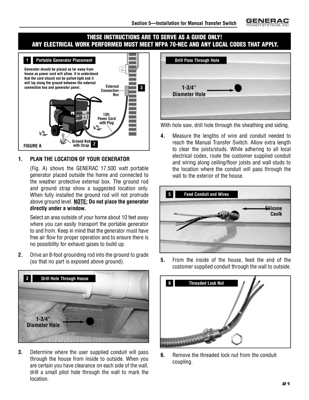
| Portable Generator Placement |
|
|
Generator should be placed as far away from |
| |||
house as power cord will allow. It is understood |
| |||
that the cord should not be pulled tight and it |
| |||
will lay along the ground between the external |
| |||
connection box and generator panel. | 3 | |||
|
|
|
|
|
FIGURE A | 2 |
|
1.PLAN THE LOCATION OF YOUR GENERATOR
(Fig. A) shows the GENERAC 17,500 watt portable generator placed outside the home and connected to the weather protective external box. The ground rod and ground strap show a suggested location only. When fully installed the ground rod will not protrude above ground level. NOTE: Do not place the generator directly under a window.
Select an area outside of your home about 10 feet away where you can easily transport the portable generator to and from. Keep in mind that the generator must have free air flow for proper operation and to ensure there is no possibility for exhaust gases to build up.
2.Drive an
3 Drill Hole Through House
Drill Pass Through Hole
Diameter Hole
With hole saw, drill hole through the sheathing and siding.
4.Measure the lengths of wire and conduit needed to reach the Manual Transfer Switch. Allow extra length to clear the joists/studs. While adhering to all local electrical codes, route the customer supplied conduit and wiring along ceiling/floor joists and wall studs to the location where the conduit will pass through the wall to the exterior of the house.
5 Feed Conduit and Wires
Silicone
Caulk
5.From the inside of the house, feed the end of the customer supplied conduit through the wall to outside.
6 |
| Threaded Lock Nut |
Diameter Hole
3.Determine where the user supplied conduit will pass through the house from inside to outside. When you are certain you have clearance on each side of the wall, drill a small pilot hole through the wall to mark the location.
6.Remove the threaded lock nut from the conduit coupling.
21