Models 04758-2 6 kW NG, 7 kW LP 04759-2 12 kW NG, 12 kW LP
04760-2 13 kW NG, 15 kW LP
This manual should remain with the unit
Installation and Owner’s Manual
‹ CONTENTS
‹ OPERATION AND MAINTENANCE
‹ HOW TO OBTAIN SERVICE
INTRODUCTION
Introduction
GENERAL HAZARDS
Despite the safe design of this generator
Parts of the generator are rotating and/or hot
during operation. Exercise care near running generators
ELECTRICAL HAZARDS
FIRE HAZARDS
EXPLOSION HAZARDS
‹ STANDARDS INDEX
1.1 UNPACKING/INSPECTION
1.2 PROTECTION SYSTEMS
1.3 SYSTEM SET LED
DANGER
Figure 1.1 - 7 kW, Single Cylinder GH-410 Engine
1.4 THE GENERATOR
Figure 1.2 - 12 kW/15 kW, V-twin GT-990/760 Engine
‹ 1.5.1 GENERATOR
1.5 SPECIFICATIONS
‹ 1.5.2 ENGINE
1.8 RECONFIGURING THE FUEL SYSTEM
1.6 FUEL REQUIREMENTS AND RECOMMENDATIONS
1.7 FUEL CONSUMPTION
DANGER
1.9 LOCATION
1.8.2 12KW AND 15KW, 990CC ENGINES
1.9.1 GENERATOR
Figure 1.4 - Demand Regulator
1.10 BATTERY INSTALLATION
1.11 THE BATTERY
1.9.2 TRANSFER SWITCH 1.9.2.1 7 kW, 12 kW and 15 kW Units
Figure 1.5 - Battery Cable Connections
2.1 BEFORE INITIAL START-UP
2.2 CHECK TRANSFER SWITCH OPERATION
2.3 ELECTRICAL CHECKS
2.4 GENERATOR TESTS UNDER LOAD
2.5 CHECKING AUTOMATIC OPERATION
Figure 2.2 - Placement of Regulator
2.6 ADJUSTING THE REGULATOR NATURAL GAS ONLY
Figure 2.1 - Dual Fuel Regulators
2.7 ENGINE GOVERNOR ADJUSTMENT
Figure 2.4 - V-twin Engine Governor Adjustment
Figure 2.3 - Single Cylinder Engine Governor Adjustment
Figure 2.5 - V-twin Full Load Speed Adjust Screw
2.8 VOLTAGE REGULATOR ADJUSTMENT
3.1 BREAK-IN PROCEDURE
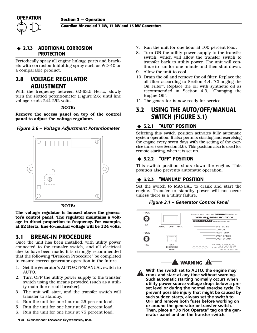
3.2 USING THE AUTO/OFF/MANUAL SWITCH FIGURE
Figure 2.6 - Voltage Adjustment Potentiometer
3.3 AUTOMATIC TRANSFER OPERATION
3.5 MANUAL TRANSFER OPERATION
3.4 SEQUENCE OF AUTOMATIC OPERATION
‹ 3.5.1 TRANSFER TO GENERATOR POWER SOURCE
‹ 3.5.2 TRANSFER BACK TO UTILITY POWER SOURCE
‹ 3.7.1 LOW OIL PRESSURE SWITCH
‹ 3.7.2 HIGH TEMPERATURE SWITCH
Figure 3.2 - Manual Transfer Switch Operation
Figure 3.3 - Low Oil Pressure and High Temperature Switches
4.2 CHECKING THE ENGINE OIL LEVEL
4.1 FUSE
‹ 3.7.3 OVERCRANK
4.5 CHANGING THE ENGINE AIR CLEANER
‹ 4.3.2 OIL CHANGE PROCEDURE
4.3 CHANGING THE ENGINE OIL
4.4 CHANGING THE OIL FILTER
4.7 BATTERY MAINTENANCE
Figure 4.6 - 7 kW, Engine Air Cleaner Location
Figure 4.7 - 12 kW and 15 kW Engine Air Cleaner
Figure 4.8 - Setting the Spark Plug Gap
Figure 4.10 - Valve Clearance Adjustment
4.8 ADJUSTING VALVE CLEARANCE
4.9 COOLING SYSTEM
4.12 OUT OF SERVICE PROCEDURE
‹ 4.12.2 RETURN TO SERVICE
‹ 4.12.1 REMOVAL FROM SERVICE
4.10 ATTENTION AFTER SUBMERSION
4.13 SERVICE SCHEDULE
5.1 TROUBLESHOOTING GUIDE
PROBLEM
CAUSE
CORRECTION
ENGINE WIRING
24 Generac Power Systems, Inc
Section 6 - Electrical Data
CUSTOMER
CONTROL PANEL BOX
CONNECTION
Electrical Schematic - 12 & 15 kW - Drawing No. 0D8501-B
26 Generac Power Systems, Inc
Generac Power Systems, Inc
28 Generac Power Systems, Inc
Section 6 - Electrical Data
Generac Power Systems, Inc
225A
30 Generac Power Systems, Inc
224A
Electrical Schematic - 7 kW - Drawing No. 0D9014-C
Section 7 - Exploded Views and Parts Lists
32 Generac Power Systems, Inc
PART NO. QTY. DESCRIPTION
34 Generac Power Systems, Inc
PART NO. QTY. DESCRIPTION
27, 28
36 Generac Power Systems, Inc
35, 36, 40
PART NO. QTY
DESCRIPTION
38 Generac Power Systems, Inc
DESCRIPTION
40 Generac Power Systems, Inc
14 20
1.8 FT
1.25 FT
42 Generac Power Systems, Inc
3 FT
2.6 FT
1.33 FT
44 Generac Power Systems, Inc
Section 7 - Exploded Views and Parts Lists
46 Generac Power Systems, Inc
Section 7 - Exploded Views and Parts Lists
48 Generac Power Systems, Inc
Section 7 - Exploded Views and Parts Lists
50 Generac Power Systems, Inc
ALL DIMENSIONS IN MILLIMETERS INCHES
Section 8 - Mounting
Guardian Air-cooled 7 kW, 12 Drawing No. 0D3739-B
Section 9 - Notes
YOUR WARRANTY RIGHTS AND OBLIGATIONS
MANUFACTURER’S EMISSION CONTROL SYSTEM WARRANTY COVERAGE
PURCHASER’S/OWNER’S WARRANTY RESPONSIBILITIES
CALIFORNIA AND FEDERAL EMISSION CONTROL WARRANTY STATEMENT
EMISSION CONTROL SYSTEM WARRANTY
EMISSION RELATED PARTS INCLUDE THE FOLLOWING
GENERAC POWER SYSTEMS TWO YEAR LIMITED WARRANTY FOR GUARDIAN
PREPACKAGED EMERGENCY AUTOMATIC STANDBY GENERATORS
WARRANTY SCHEDULE
THIS WARRANTY SHALL NOT APPLY TO THE FOLLOWING