Section 7

DIAGNOSTIC TESTS

0000

CONTINUITY

87

14

25

36

DEPRESSED

AWAY FROM

TERMINAL BEING

TESTED

5.Connect the VOM positive (+) test lead to Wire 56 (Pin Location J1-9) at the Printed Circuit Board. Connect the other test lead to frame ground.

6.Actuate the Start-Stop Switch to the “START” position. The meter should indicate battery volt- age.

RESULTS:

1.If battery voltage was measured in Step 6, but not in Step 4, repair or replace Wire 56 between the Printed Circuit Board and Starter Contactor Relay.

2.If battery voltage was not available in Step 6, replace the Printed Circuit Board.

3.If battery voltage is available in Step 4 but engine does not crank, go to Test 22.

Test 22 – Check Starter Contactor

Relay

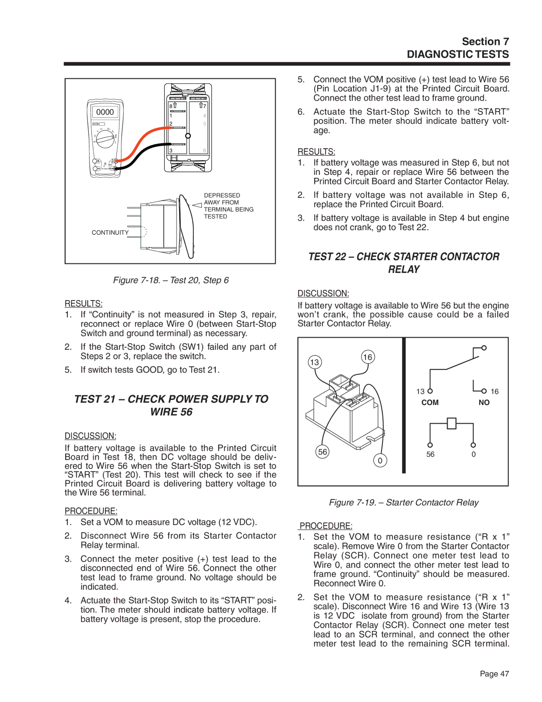
Figure 7-18. – Test 20, Step 6

RESULTS:

1.If “Continuity” is not measured in Step 3, repair, reconnect or replace Wire 0 (between Start-Stop Switch and ground terminal) as necessary.

2.If the Start-Stop Switch (SW1) failed any part of Steps 2 or 3, replace the switch.

5. If switch tests GOOD, go to Test 21.

Test 21 – Check Power Supply to

Wire 56

DISCUSSION:

If battery voltage is available to the Printed Circuit Board in Test 18, then DC voltage should be deliv- ered to Wire 56 when the Start-Stop Switch is set to “START” (Test 20). This test will check to see if the Printed Circuit Board is delivering battery voltage to the Wire 56 terminal.

PROCEDURE:

1.Set a VOM to measure DC voltage (12 VDC).

2.Disconnect Wire 56 from its Starter Contactor Relay terminal.

3.Connect the meter positive (+) test lead to the disconnected end of Wire 56. Connect the other test lead to frame ground. No voltage should be indicated.

4.Actuate the Start-Stop Switch to its “START” posi- tion. The meter should indicate battery voltage. If battery voltage is present, stop the procedure.

DISCUSSION:

If battery voltage is available to Wire 56 but the engine won’t crank, the possible cause could be a failed Starter Contactor Relay.

1316

13

16

COM

NO

56

56

0

0

Figure 7-19. – Starter Contactor Relay

PROCEDURE:

1.Set the VOM to measure resistance (“R x 1” scale). Remove Wire 0 from the Starter Contactor Relay (SCR). Connect one meter test lead to Wire 0, and connect the other meter test lead to frame ground. “Continuity” should be measured. Reconnect Wire 0.

2.Set the VOM to measure resistance (“R x 1” scale). Disconnect Wire 16 and Wire 13 (Wire 13 is 12 VDC isolate from ground) from the Starter Contactor Relay (SCR). Connect one meter test lead to an SCR terminal, and connect the other meter test lead to the remaining SCR terminal.

Page 47

Page 49
Image 49
Generac Power Systems 5411, 5412, 5413, 5415, 5414 Test 22 Check Starter Contactor Relay, Test 21 Check Power Supply to Wire

5410, 5414, 5415, 5413, 5411 specifications

Generac Power Systems has established itself as a leading manufacturer of backup power solutions, particularly known for its range of generators designed for both residential and commercial use. Among their noteworthy products are the Generac models 5412, 5411, 5413, 5415, and 5414. Each of these generators showcases innovative technologies and features that enhance reliability, efficiency, and ease of use.

The Generac 5412 is a versatile model equipped with a robust 10 kW output, making it suitable for powering essential home appliances during outages. It operates using a 1.0 L engine that runs on natural gas or propane, providing flexibility in fuel options. The Quiet-Test feature is a notable characteristic, as it allows for a self-test at a reduced volume, minimizing noise disruptions during routine checks.

Moving to the Generac 5411, this generator offers a higher output capacity of 13 kW. It integrates advanced load management technology, which ensures that power is allocated efficiently among connected devices. This model also features a Mobile Link remote monitoring system, enabling users to check generator status and performance from anywhere via a smartphone app.

The Generac 5413 is tailored for larger residential needs, delivering an impressive 16 kW output. It boasts a durable all-weather aluminum enclosure designed for longevity against the elements. The 5413's integrated wifi connectivity allows for real-time monitoring and alerts, ensuring that homeowners are always informed of their generator's operating status.

For those seeking a balance of power and efficiency, the Generac 5415 offers 20 kW of output while maintaining a compact design. This model is enriched with the patented G-Flex technology, allowing it to adjust engine speed based on the load requirements, thereby conserving fuel and reducing noise levels. Additionally, the 5415 comes with an intuitive user interface for effortless operation and programming.

Finally, the Generac 5414 rounds out the lineup with its strong 24 kW capability. This model is particularly known for its Smart Management modules, which facilitate the safe and efficient distribution of power. Its intuitive design also includes a user-friendly control panel for straightforward operation, ensuring that homeowners, regardless of technical expertise, can utilize the system effectively.

In summary, Generac Power Systems’ 5412, 5411, 5413, 5415, and 5414 generators exemplify advanced power technology, tailored for reliability and user convenience. Whether for essential home functions or more extensive power needs, these models provide effective solutions to ensure that homes remain powered during outages.