VERTICAL DEFLECTION CIRCUIT, FUNCTION, DESCRIPTION.

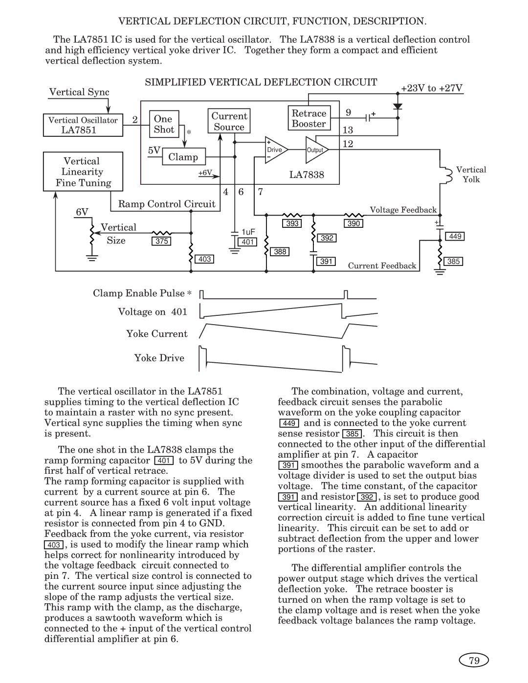
The LA7851 IC is used for the vertical oscillator. The LA7838 is a vertical deflection control and high efficiency vertical yoke driver IC. Together they form a compact and efficient vertical deflection system.

Vertical Sync


SIMPLIFIED VERTICAL DEFLECTION CIRCUIT

+23V to +27V


Vertical Oscillator

2

One


Current


Retrace

9


Booster


LA7851


Shot

*

Source


13


12


5V Clamp


Drive

Output


Vertical


Vertical

Linearity


+6V


LA7838


Fine Tuning


Yolk


4

6

7


6V

Ramp Control Circuit


Voltage Feedback


Vertical


1uF


393

390


+


449

Size


392


375


401


403


388


391

Current Feedback

385


Clamp Enable Pulse *

Voltage on 401

Yoke Current

Yoke Drive

The vertical oscillator in the LA7851 supplies timing to the vertical deflection IC to maintain a raster with no sync present. Vertical sync supplies the timing when sync is present.

The one shot in the LA7838 clamps the ramp forming capacitor 401 to 5V during the first half of vertical retrace.

The ramp forming capacitor is supplied with current by a current source at pin 6. The current source has a fixed 6 volt input voltage at pin 4. A linear ramp is generated if a fixed resistor is connected from pin 4 to GND. Feedback from the yoke current, via resistor

403, is used to modify the linear ramp which helps correct for nonlinearity introduced by the voltage feedback circuit connected to pin 7. The vertical size control is connected to the current source input since adjusting the slope of the ramp adjusts the vertical size. This ramp with the clamp, as the discharge, produces a sawtooth waveform which is connected to the + input of the vertical control differential amplifier at pin 6.

The combination, voltage and current, feedback circuit senses the parabolic waveform on the yoke coupling capacitor

449and is connected to the yoke current sense resistor 385 . This circuit is then connected to the other input of the differential amplifier at pin 7. A capacitor

391smoothes the parabolic waveform and a voltage divider is used to set the output bias voltage. The time constant, of the capacitor 391 and resistor 392 , is set to produce good vertical linearity. An additional linearity correction circuit is added to fine tune vertical linearity. This circuit can be set to add or subtract deflection from the upper and lower portions of the raster.

The differential amplifier controls the power output stage which drives the vertical deflection yoke. The retrace booster is turned on when the ramp voltage is set to the clamp voltage and is reset when the yoke feedback voltage balances the ramp voltage.

79

Page 63
Image 63
Genius ISO XFR-100W, ISO XFR-75W, 2093, 1493, 2793, 3693, 1793, 1993 manual Vertical Deflection CIRCUIT, FUNCTION, Description

2093, 1493, ISO XFR-75W, 3693, 2793 specifications

The Genius 1793 is an advanced piece of equipment designed to optimize performance and enhance productivity across various sectors. Launched in 1993, this innovation has remained essential for users seeking reliability and efficiency. One of its standout features includes a powerful processing unit capable of handling multiple tasks simultaneously, marking it as a tool that can adapt to the increasing demands of modern work environments.

Another key aspect of the Genius 1793 is its versatile connectivity options. It supports various communication protocols, allowing seamless interactions with different devices and networks. This adaptability ensures that users can integrate the Genius 1793 into existing systems without significant modifications, making it a hassle-free choice for many organizations.

ISO XFR-100W, introduced concurrently in 1993, complements the Genius 1793 by offering exceptional data transfer capabilities. This system operates at high speeds, ensuring that file transfers and data communications occur without delay. Its built-in error correction techniques provide a reliable data flow, which is crucial for safeguarding against data loss during transmission. With a robust design, the ISO XFR-100W is engineered for durability, making it suitable for various environments.

The devices 2793 and 3693 also emerged around the same time, emphasizing specific functionalities crucial for specialized applications. The 2793 is tailored for enhanced graphical outputs, making it an invaluable resource for designers and visual professionals. Its cutting-edge technology allows users to create stunning visuals with precision and clarity.

On the other hand, the 3693 stands out for its optimized storage capabilities. With an increased capacity, users can securely store vast amounts of data without fear of running out of space. Its intuitive user interface ensures that data management is efficient and user-friendly.

Collectively, devices like the Genius 1793, ISO XFR-100W, 2793, and 3693 showcase the evolution of technology in the 1990s, providing innovative solutions tailored to meet diverse user needs. Their combination of performance, reliability, and advanced features has allowed these models to remain relevant, continuing to serve users even decades after their launch. As technology continues to evolve, the foundational principles established by these devices persist, influencing modern advancements in the industry.