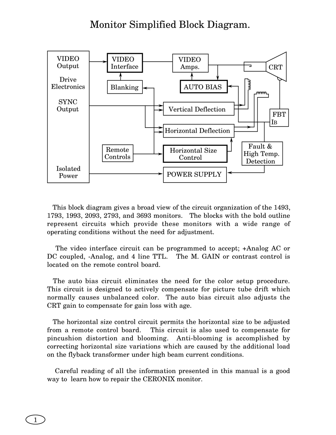
2093, 1493, ISO XFR-75W, 3693, 2793 specifications
The Genius 1793 is an advanced piece of equipment designed to optimize performance and enhance productivity across various sectors. Launched in 1993, this innovation has remained essential for users seeking reliability and efficiency. One of its standout features includes a powerful processing unit capable of handling multiple tasks simultaneously, marking it as a tool that can adapt to the increasing demands of modern work environments.Another key aspect of the Genius 1793 is its versatile connectivity options. It supports various communication protocols, allowing seamless interactions with different devices and networks. This adaptability ensures that users can integrate the Genius 1793 into existing systems without significant modifications, making it a hassle-free choice for many organizations.
ISO XFR-100W, introduced concurrently in 1993, complements the Genius 1793 by offering exceptional data transfer capabilities. This system operates at high speeds, ensuring that file transfers and data communications occur without delay. Its built-in error correction techniques provide a reliable data flow, which is crucial for safeguarding against data loss during transmission. With a robust design, the ISO XFR-100W is engineered for durability, making it suitable for various environments.
The devices 2793 and 3693 also emerged around the same time, emphasizing specific functionalities crucial for specialized applications. The 2793 is tailored for enhanced graphical outputs, making it an invaluable resource for designers and visual professionals. Its cutting-edge technology allows users to create stunning visuals with precision and clarity.
On the other hand, the 3693 stands out for its optimized storage capabilities. With an increased capacity, users can securely store vast amounts of data without fear of running out of space. Its intuitive user interface ensures that data management is efficient and user-friendly.
Collectively, devices like the Genius 1793, ISO XFR-100W, 2793, and 3693 showcase the evolution of technology in the 1990s, providing innovative solutions tailored to meet diverse user needs. Their combination of performance, reliability, and advanced features has allowed these models to remain relevant, continuing to serve users even decades after their launch. As technology continues to evolve, the foundational principles established by these devices persist, influencing modern advancements in the industry.

